Content .. 1541 1542 1543 1544 ..
Toyota Tundra (2015 year). Manual - part 1543
OK
OK
26.
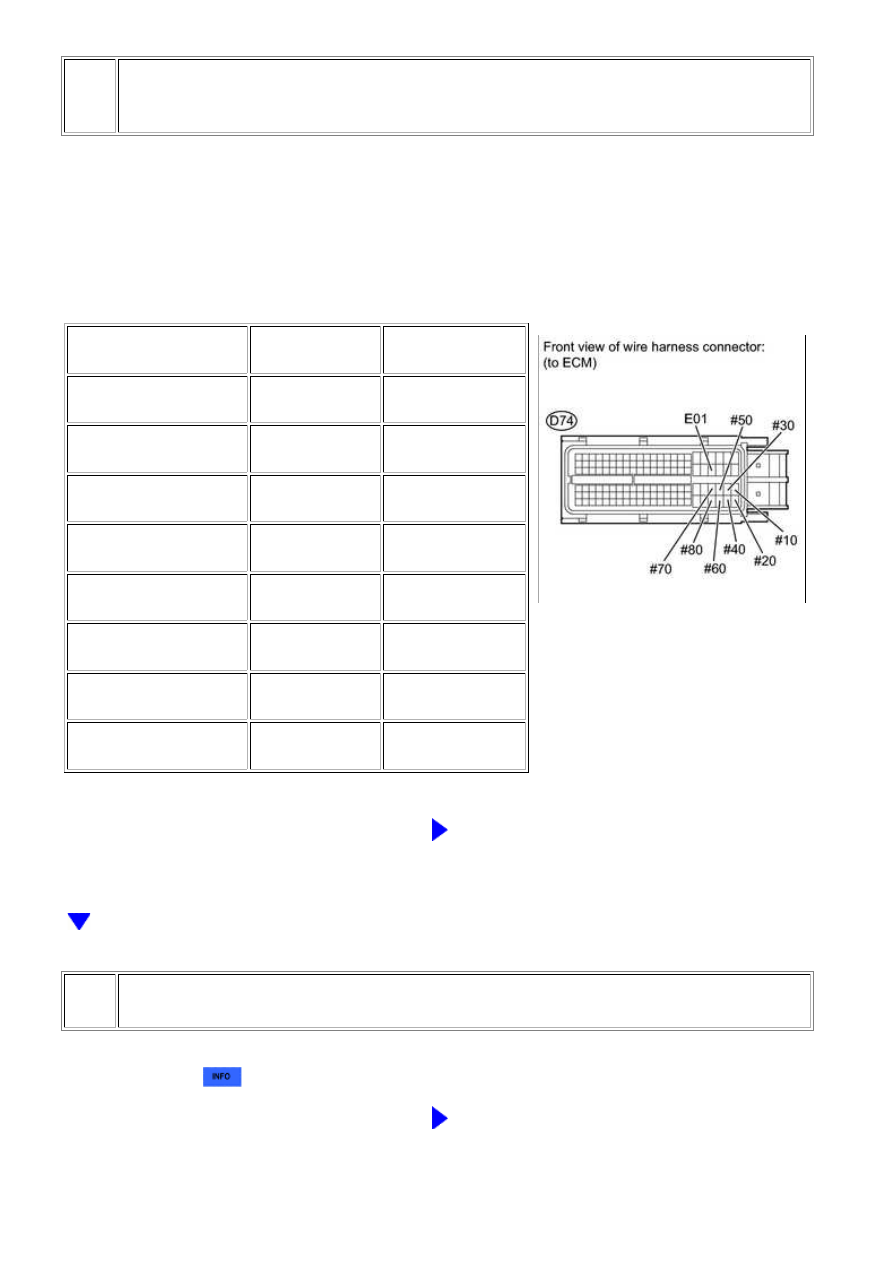
INSPECT ECM TERMINAL OF MISFIRING CYLINDER (#10, #20, #30, #40, #50,
#60, #70 AND/OR #80 VOLTAGE)
(a) Disconnect the D74 ECM connector.
(b) Turn the ignition switch to ON.
(c) Measure the voltage according to the value(s) in the
table below.
Standard voltage:
TESTER CONNECTION
SWITCH
CONDITION
SPECIFIED
CONDITION
D74-86 (#10) - D74-43
(E01)
Ignition switch ON
11 to 14 V
D74-109 (#20) - D74-43
(E01)
Ignition switch ON
11 to 14 V
D74-85 (#30) - D74-43
(E01)
Ignition switch ON
11 to 14 V
D74-108 (#40) - D74-43
(E01)
Ignition switch ON
11 to 14 V
D74-84 (#50) - D74-43
(E01)
Ignition switch ON
11 to 14 V
D74-107 (#60) - D74-43
(E01)
Ignition switch ON
11 to 14 V
D74-83 (#70) - D74-43
(E01)
Ignition switch ON
11 to 14 V
D74-106 (#80) - D74-43
(E01)
Ignition switch ON
11 to 14 V
NG
GO TO FUEL INJECTOR CIRCUIT
27.
CHECK FUEL INJECTOR OF MISFIRING CYLINDER
(a) Check the fuel injector injection [whether fuel volume is high or low, and whether injection
pattern is poor]
.
NG
REPLACE FUEL INJECTOR ASSEMBLY
3UR-FBE ENGINE CONTROL SYSTEM: SFI SYSTEM: P0300-P030...