Content .. 1415 1416 1417 1418 ..
Toyota Tundra (2015 year). Manual - part 1417
(b) Install the water inlet housing with the 3 bolts.
Torque:
21 N·m {214 kgf·cm, 15ft·lbf}
17. CONNECT NO. 5 WATER BY-PASS HOSE
18. CONNECT NO. 8 WATER BY-PASS HOSE
19. INSTALL WATER BY-PASS PIPE SUB-ASSEMBLY
(a) Connect the No. 2 water by-pass hose to the water by-pass pipe sub-assembly, and slide the clamp to
secure the hose.
(b) Install the water by-pass pipe sub-assembly to the cylinder head cover sub-assembly RH with the 2 bolts.
Torque:
10 N·m {102 kgf·cm, 7ft·lbf}
20. INSTALL AIR TUBE SUB-ASSEMBLY RH
(a) Install the air tube sub-assembly RH to the cylinder head cover sub-assembly RH with the 2 bolts.
Torque:
10 N·m {102 kgf·cm, 7ft·lbf}
21. INSTALL NO. 1 WATER BY-PASS HOSE
22. INSTALL NO. 3 ENGINE COVER
23. INSTALL NO. 4 ENGINE COVER
24. INSTALL GENERATOR ASSEMBLY
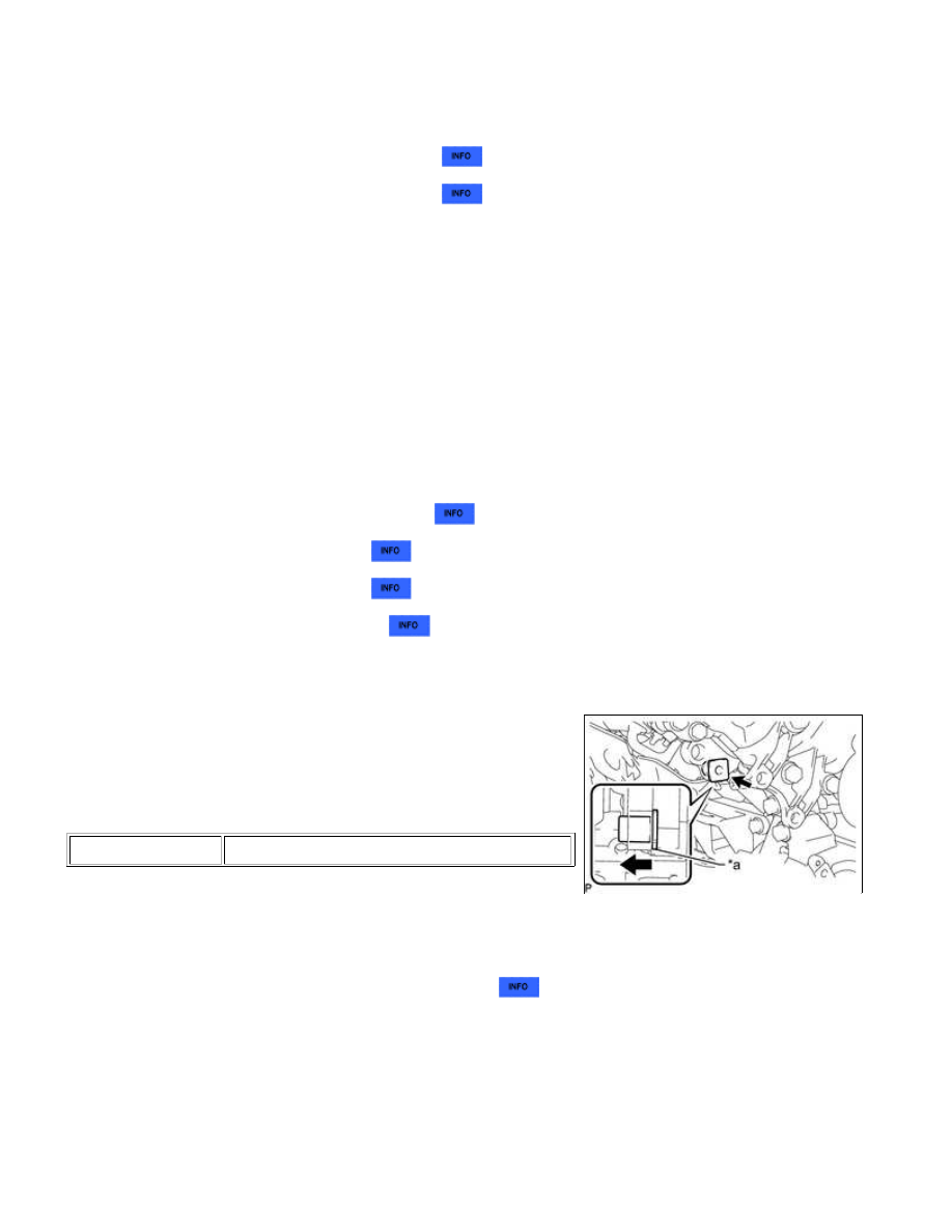
25. CONNECT VANE PUMP ASSEMBLY
(a) Connect the vane pump assembly to the timing chain cover
sub-assembly with the 2 bolts.
Torque:
28 N·m {286 kgf·cm, 21ft·lbf}
Text in Illustration
*a
Spacer
HINT:
Before performing the following procedures, move the spacer
until the vane pump assembly can be installed.
26. INSTALL ENGINE OIL LEVEL DIPSTICK GUIDE
27. INSTALL OIL FILTER BRACKET
(c) Install the oil filter bracket to the timing chain cover sub-assembly with the 2 nuts and 2 bolts.
Torque:
35 N·m {357 kgf·cm, 26ft·lbf}
1UR-FE LUBRICATION: OIL PUMP: INSTALLATION; 2015 MY Tun...