Toyota Tundra (2015 year). Manual - part 1109


  Index      Toyota     Toyota Tundra (2015 year) - Service and Repair Manual


Search            copyright infringement  


Content   ..  1107  1108  1109  1110   ..


Toyota Tundra (2015 year). Manual - part 1109
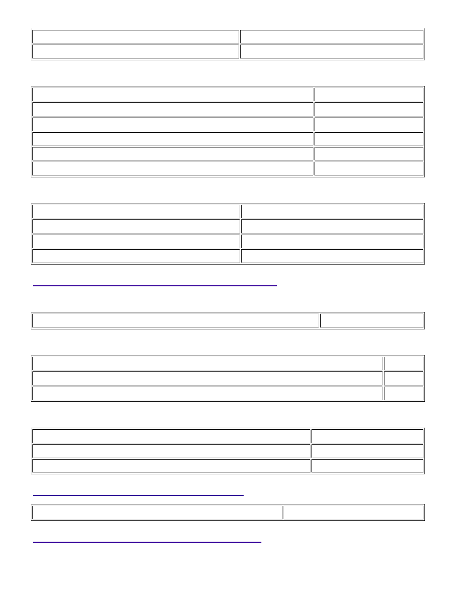


Output duty cycle

30% or more

P0032 and P0052

Monitor runs whenever following DTCs not stored

None

Battery voltage

10.5 V or higher

Time after heater on

5 seconds or more

Active heater OFF control

Not operating

Active heater ON control

Not operating

Air fuel ratio sensor heater duty-cycle

More than 0%

P101D and P103D

Monitor runs whenever following DTCs not stored

P0031, P0051 (Air fuel ratio sensor heater)

Battery voltage

10.5 V or higher

Active heater OFF control

Not operating

Active heater ON control

Not operating

TYPICAL MALFUNCTION THRESHOLDS

P0031 and P0051

Air fuel ratio sensor heater current

Below 0.8 A

P0032 and P0052

Air fuel ratio sensor heater output

ON

Hybrid IC high current limiter monitor

Fail

P101D and P103D

Air fuel ratio sensor heater OFF current

Higher than 11 A

Hybrid IC high current limiter monitor input

Fail

COMPONENT OPERATING RANGE

A/F sensor heater current

0.8 A or more

CONFIRMATION DRIVING PATTERN

1UR-FE ENGINE CONTROL SYSTEM: SFI SYSTEM: P0031,P0032,...

Connect the Techstream to the DLC3.

1. 

Turn the ignition switch to ON and turn the Techstream ON.

2. 

Clear DTCs (even if no DTCs are stored, perform the clear DTC operation).

3. 

Turn the ignition switch off and wait for at least 30 seconds.

4. 

Turn the ignition switch to ON and turn the Techstream on [A].

5. 

Start the engine and idle it for 5 minutes or more [B].

6. 

7. 

Idle the engine for 5 minutes or more [D].

8. 

Enter the following menus: Powertrain / Engine and ECT / Trouble Codes [E].

9. 

Read the pending DTCs.

HINT:

If a pending DTC is output, the system is malfunctioning.
If a pending DTC is not output, perform the following procedure.

10. 

Enter the following menus: Powertrain / Engine and ECT / Utility / All Readiness.

11. 

Input the DTC: P0031, P0032, P0051, P0052, P101D or P103D.

12. 

Check the DTC judgment result.

TESTER

DISPLAY

DESCRIPTION

NORMAL

DTC judgment completed

System normal

ABNORMAL

DTC judgment completed

System abnormal

INCOMPLETE

DTC judgment not completed

Perform driving pattern after confirming DTC enabling conditions

13. 

1UR-FE ENGINE CONTROL SYSTEM: SFI SYSTEM: P0031,P0032,...

OK

TESTER

DISPLAY

DESCRIPTION

N/A

Unable to perform DTC judgment

If the judgment result shows INCOMPLETE or N/A, perform steps [B] through [E] again.

14. 

If no pending DTC is output, perform a universal trip and check for permanent DTCs 


.

HINT:

If a permanent DTC is output, the system is malfunctioning.
If no permanent DTC is output, the system is normal.

15. 

WIRING DIAGRAM

Refer to DTC P2195 


.

INSPECTION PROCEDURE

HINT:

Bank 1 refers to the bank that includes the No. 1 cylinder*.

*: The No. 1 cylinder is the cylinder which is farthest from the transmission.

Bank 2 refers to the bank that does not include the No. 1 cylinder.
Sensor 1 refers to the sensor closest to the engine assembly.
Sensor 2 refers to the sensor farthest away from the engine assembly.
Change the fuel injection volume using the Control the Injection Volume function provided in the Active
Test and monitor the air fuel ratio sensor output voltage 


. If the sensor output voltage does not

change (almost no reaction) while performing the Active Test, the sensor may be malfunctioning.
Read freeze frame data using the Techstream. Freeze frame data records the engine condition when
malfunctions are detected. When troubleshooting, freeze frame data can help determine if the vehicle was
moving or stationary, if the engine was warmed up or not, if the air-fuel ratio was lean or rich, and other
data from the time the malfunction occurred.

PROCEDURE

1.

INSPECT AIR FUEL RATIO SENSOR (HEATER RESISTANCE)

(a) Inspect the air fuel ratio sensor 


.

HINT:

Perform "Inspection After Repair" after replacing the air fuel ratio sensor 


.

NG

REPLACE AIR FUEL RATIO SENSOR

1UR-FE ENGINE CONTROL SYSTEM: SFI SYSTEM: P0031,P0032,...

A

2.

CHECK TERMINAL VOLTAGE (+B OF A/F SENSOR)

(a) Disconnect the A/F sensor connector.

(b) Turn the ignition switch to ON.

(c) Measure the voltage according to the value(s) in the table

below.

Standard Voltage:

TESTER CONNECTION

SWITCH

CONDITION

SPECIFIED

CONDITION

D33-2 (+B) - Body

ground

Ignition switch ON

11 to 14 V

D34-2 (+B) - Body

ground

Ignition switch ON

11 to 14 V

Result

RESULT

PROCEED TO

NG

A

OK

B

B

GO TO STEP 5

3.

INSPECT INTEGRATION RELAY (A/F)

1UR-FE ENGINE CONTROL SYSTEM: SFI SYSTEM: P0031,P0032,...


Content   ..  1107  1108  1109  1110   ..