Toyota Tundra. Manual - part 931
 

  Index      Toyota     Toyota Tundra (2007-2010 year) - Service and Repair Manual


Search            copyright infringement  


Content   ..  929  930  931  932   ..


Toyota Tundra. Manual - part 931


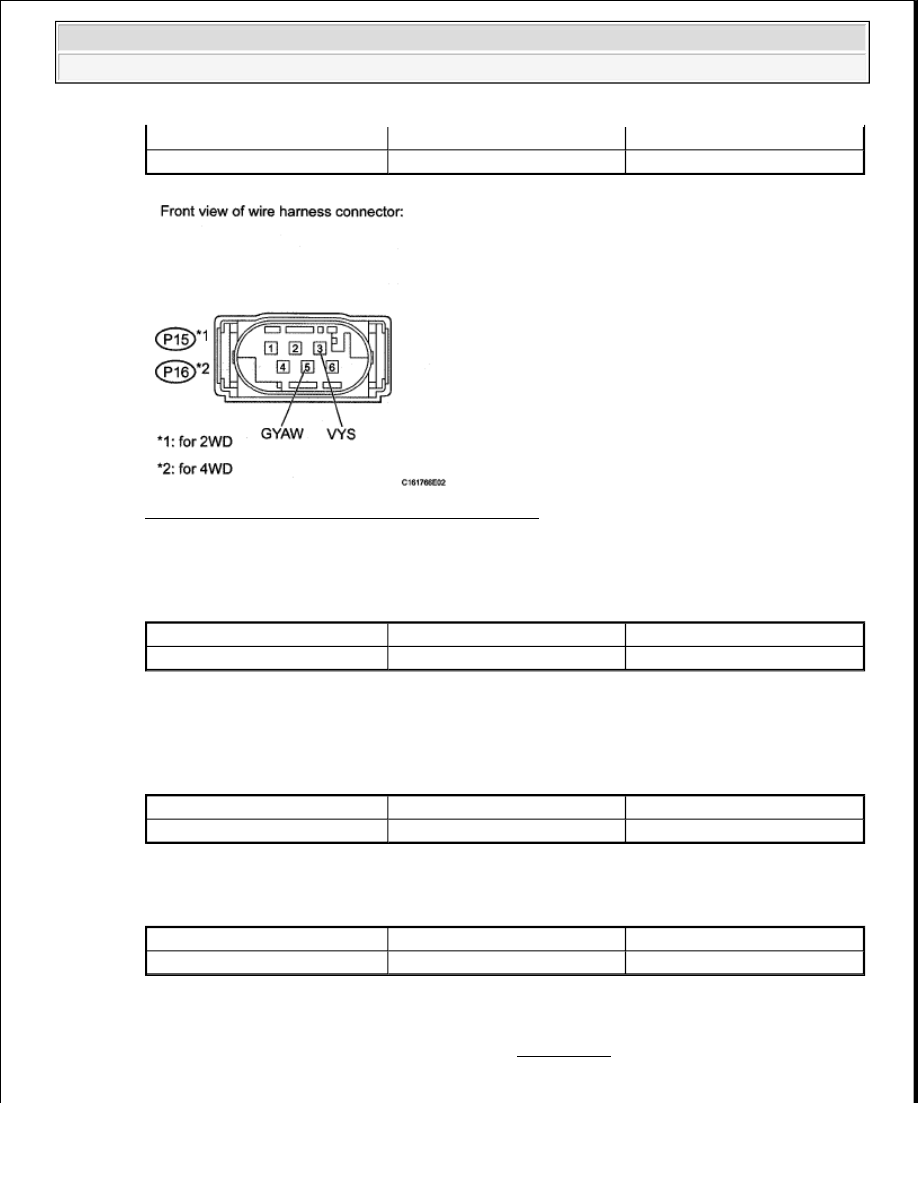
Fig. 51: Identifying P15 And P16 Sensor Connector 
Courtesy of TOYOTA MOTOR SALES, U.S.A., INC. 

for 4WD  

TESTER CONNECTION SPECIFIED CONDITION TABLE 

d. Measure the resistance according to the value (s) in the table below. 

Standard Resistance: for 2WD  

TESTER CONNECTION SPECIFIED CONDITION TABLE 

for 4WD  

TESTER CONNECTION SPECIFIED CONDITION TABLE 

NG: REPAIR OR REPLACE HARNESS OR CONNECTOR  

OK: REPLACE VSC ACTUATOR ASSEMBLY (See REMOVAL ) 

Tester Connection

Switch Condition

Specified Condition

P15-3 (VYS) - P15-5 (GYAW)

Ignition switch ON

11 to 14 V

Tester Connection

Switch Condition

Specified Condition

P16-3 (VYS) - P16-5 (GYAW)

Ignition switch ON

11 to 14 V

Tester Connection

Switch Condition

Specified Condition

P15-5 (GYAW) - Body ground

Ignition switch ON

Below 1 ohms

Tester Connection

Switch Condition

Specified Condition

P16-5 (GYAW) - Body ground

Ignition switch ON

Below 1 ohms


2009 Toyota Tundra 

2009 BRAKES Brake Control - Tundra


DTC C1201/51: ENGINE CONTROL SYSTEM MALFUNCTION 

DESCRIPTION 

If a malfunction in the engine control system is detected through the CAN, the operations of VSC and TRAC 
are prohibited by the fail-safe function. When the signals from the engine are input normally, the fail-safe is 
canceled and the DTC is stored. 

DTC DETECTION CONDITION TABLE 

INSPECTION PROCEDURE 

1. CHECK DTC (FOR SFI SYSTEM) 

a. for 1GR-FE: 

Clear the DTC (SFI system) (See DTC CHECK/CLEAR ). 

Clear the DTC (SFI system) (See DTC CHECK/CLEAR ). 

Clear the DTC (SFI system) (See DTC CHECK/CLEAR ). 

b. for 1GR-FE: 

Check the DTC (SFI system) (See DTC CHECK/CLEAR ). 

Check the DTC (SFI system) (See DTC CHECK/CLEAR ). 

Check the DTC (SFI system) (See DTC CHECK/CLEAR ). 

Result  

RESULT TABLE 

B: GO TO SFI SYSTEM (See DIAGNOSTIC TROUBLE CODE TABLE ) 

DTC Code

DTC Detection Condition

Trouble Area

C1201/51

Engine control system malfunction 
signal continues for 1.2 seconds.

SFI system

NOTE:

When replacing the VSC actuator assembly, perform zero point calibration (See 
CALIBRATION ).

Result

Proceed to

DTC (SFI system) is not output

A

DTC (SFI system) is output (for 1GR-FE)

B

DTC (SFI system) is output (for 2UZ-FE)

C

DTC (SFI system) is output (for 3UR-FE)

D


2009 Toyota Tundra 

2009 BRAKES Brake Control - Tundra


C: GO TO SFI SYSTEM (See DIAGNOSTIC TROUBLE CODE TABLE ) 

D: GO TO SFI SYSTEM (See DIAGNOSTIC TROUBLE CODE TABLE ) 

A: USE SIMULATION METHOD TO CHECK (See HOW TO PROCEED WITH 
TROUBLESHOOTING
 ) 

DTC C1203/53: ECM COMMUNICATION CIRCUIT MALFUNCTION 

DESCRIPTION 

A new skid control ECU is supplied without engine variation data. Until it is recognized by the ECU, DTC 
C1203/53 remains stored. By entering test mode, recognition of engine variation data is automatically 
conducted, and DTC C1203/53 is erased automatically. 

DTC DETECTION CONDITION TABLE 

INSPECTION PROCEDURE 

1. PERFORM TEST MODE INSPECTION 

a. Perform TEST MODE PROCEDURE .  

2. RECONFIRM DTC 

a. Clear the DTC (See DTC CHECK/CLEAR ).  

b. Start the engine.  

c. Check if the same DTC is output (See DTC CHECK/CLEAR ). 

Result  

RESULT TABLE 

DTC Code

DTC Detection Condition

Trouble Area

C1203/53

When all of following conditions 
detected: 

1. Engine variation data from 

ECM does not match one in 
skid control ECU non-
volatile memory.  

2. DTC U0073/94 not detected. 

3. DTC U0100/65 not detected. 

Test mode not performed  

Skid control ECU  

NOTE:

When replacing the VSC actuator assembly, perform zero point calibration (See 
CALIBRATION ).

Result

Proceed to

DTC is output

A


2009 Toyota Tundra 

2009 BRAKES Brake Control - Tundra


B: USE SIMULATION METHOD TO CHECK (See HOW TO PROCEED WITH 
TROUBLESHOOTING
 ) 

A: REPLACE VSC ACTUATOR ASSEMBLY (See REMOVAL ) 

DTC C1207/37: MALFUNCTION IN PARK/NEUTRAL POSITION SWITCH 

DESCRIPTION 

The park/neutral position switch signal is sent to the skid control ECU via the CAN communication system. 

When there is a malfunction in the CAN communication system, it will be detected by the diagnostic function. 

DTC DETECTION CONDITION TABLE 

WIRING DIAGRAM 

DTC is not output

B

DTC Code

DTC Detection Condition

Trouble Area

C1207/37

When all conditions below are 
met: 

Yaw rate sensor is normal.  

G sensor lateral operation is 
normal.  

Vehicle speed is 40 km/h 
(24.9 mph) or more.  

Reversing signal is output 
from ECM for 1 second or 
more.  

Park/Neutral position switch  

ECM  

CAN communication system  

Harness or connector  

Skid control ECU  


2009 Toyota Tundra 

2009 BRAKES Brake Control - Tundra


Content   ..  929  930  931  932   ..