Toyota Tundra. Manual - part 568
 

  Index      Toyota     Toyota Tundra (2007-2010 year) - Service and Repair Manual


Search            copyright infringement  


Content   ..  566  567  568  569   ..


Toyota Tundra. Manual - part 568


NG: TURN MUTE SWITCH OFF  

OK: Go to Next Step  

3. CHECK SETTINGS 

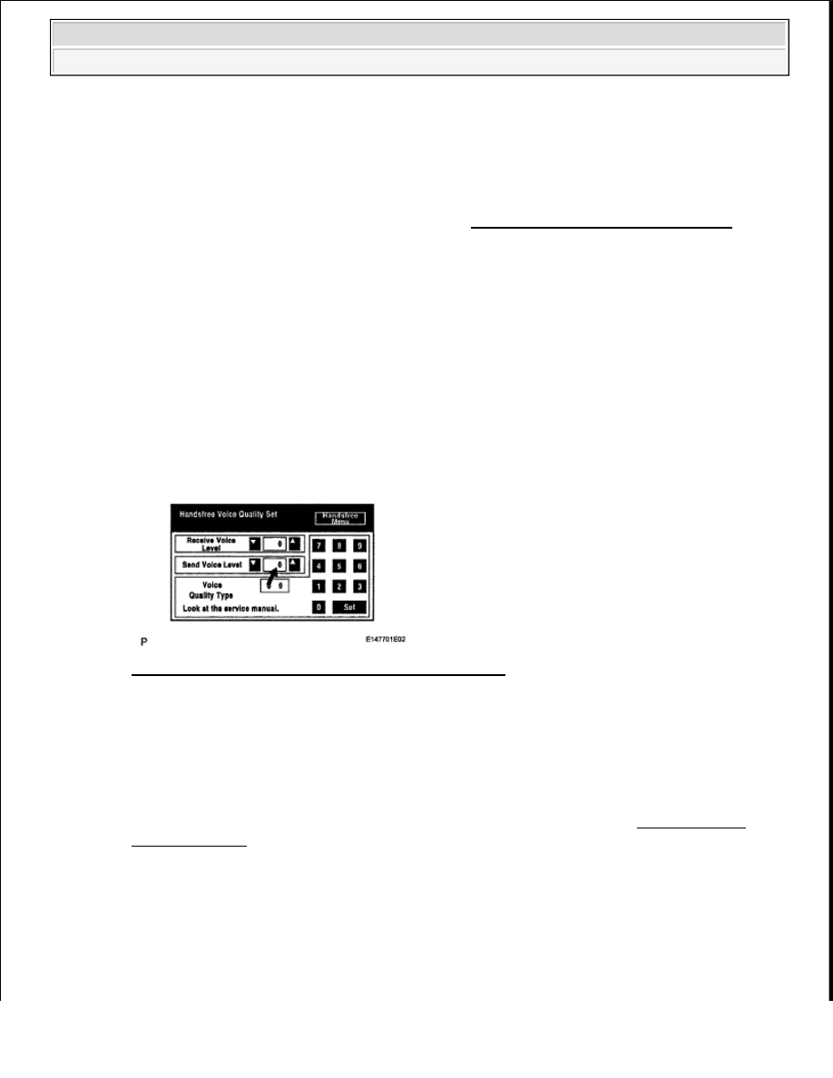
a. Enter the "Handsfree Voice Quality Set" mode (see BLUETOOTH TEL CHECK MODE ).  

b. Check if the Send Voice Level is set to "0". 

HINT: 

The Send Voice Level can be set to 11 different levels, -5 to +5, with a 3 dB difference. 

c. Check if the Send Voice Level is set to the minimum or maximum level. 

HINT: 

When the Send Voice Level is set to the minimum or maximum level, the sound may be distorted. 

OK: The Send Voice Level is set to "0".  

Fig. 389: Display - Handsfree Voice Quality Set Mode 
Courtesy of TOYOTA MOTOR SALES, U.S.A., INC. 

NG: SET SEND VOICE LEVEL TO "0"  

OK: Go to Next Step  

4. CHECK MICROPHONE (NAVIGATION CHECK MODE) 

a. Enter the "MICROPHONE & VOICE RECOGNITION CHECK" mode (see NAVIGATION 

CHECK MODE ).  

b. When a voice is input into the microphone, check that the microphone input level meter changes 

according to the input voice.  

c. Push the recording switch and perform voice recording. 

HINT: 

The recording limit is 5 seconds. 


2009 Toyota Tundra 

2009 ACCESSORIES AND EQUIPMENT Navigation - Tundra


d. Check that the recording indicator remains on while recording and that the recorded voice is played 

normally without noise or distortion. 

OK: All check results are normal.  

Result  

MICROPHONE (NAVIGATION CHECK MODE) RESULT CHART 

Fig. 390: Display - Microphone Voice Recognition Check Mode 
Courtesy of TOYOTA MOTOR SALES, U.S.A., INC. 

B: REPLACE NAVIGATION RECEIVER (see REMOVAL (For Floor Shift Type) ) 

C: PROCEED TO NEXT CIRCUIT INSPECTION SHOWN IN PROBLEM SYMPTOMS TABLE 

A: REPLACE NAVIGATION RECEIVER (see REMOVAL (For Column Shift Type) ) 

VEHICLE SPEED SIGNAL CIRCUIT BETWEEN NAVIGATION RECEIVER ASSEMBLY AND 
COMBINATION METER 

DESCRIPTION 

This circuit sends a speed signal from the combination meter to the navigation receiver. 

HINT: 

A voltage of 12 V or 5 V is output from each ECU and then input to the combination meter. The signal is 

Result

Proceed to

OK (for Column Shift Type)

A

OK (for Floor Shift Type)

B

NG

C


2009 Toyota Tundra 

2009 ACCESSORIES AND EQUIPMENT Navigation - Tundra


changed to a pulse signal at the transistor in the combination meter. Each ECU controls its respective 
system based on the pulse signal.  

If a short occurs in any of the ECUs or in the wire harness connected to an ECU, both systems in the 
diagram below will not operate normally.  

WIRING DIAGRAM 

Fig. 391: Vehicle Speed Signal Circuit between Navigation Receiver Assembly and Combination Meter - 
Wiring Diagram
 
Courtesy of TOYOTA MOTOR SALES, U.S.A., INC. 

INSPECTION PROCEDURE 

1. CHECK OPERATION OF SPEEDOMETER 

a. Drive the vehicle and check if the function of the speedometer in the combination meter is normal. 

OK: Actual vehicle speed and the speed indicated on the speedometer are the same.  

HINT: 

The vehicle speed sensor is functioning normally when the indication on the speedometer is 
normal. 

NG: Go TO METER / GAUGE SYSTEM (See HOW TO PROCEED WITH 
TROUBLESHOOTING
 ) 

OK: Go to Next Step  

2. CHECK HARNESS AND CONNECTOR (NAVIGATION RECEIVER - COMBINATION 

METER) 

a. Disconnect the K6 receiver connector.  

b. Disconnect the J28 meter connector.  

c. Measure the resistance according to the value(s) in the table below. 

Standard resistance  

HARNESS AND CONNECTOR (NAVIGATION RECEIVER - COMBINATION METER) 
TESTER CONNECTION SPECIFIED CONDITION
 

Tester Connection

Condition Specified Condition


2009 Toyota Tundra 

2009 ACCESSORIES AND EQUIPMENT Navigation - Tundra


Result  

HARNESS AND CONNECTOR (NAVIGATION RECEIVER - COMBINATION METER) 
RESULT CHART
 

Fig. 392: Identifying K6 Receiver Connector And J28 Meter Connector 
Courtesy of TOYOTA MOTOR SALES, U.S.A., INC. 

B: REPLACE NAVIGATION RECEIVER (see REMOVAL (For Floor Shift Type) ) 

C: REPAIR OR REPLACE HARNESS OR CONNECTOR  

A: REPLACE NAVIGATION RECEIVER (see REMOVAL (For Column Shift Type) ) 

STEERING PAD SWITCH CIRCUIT 

DESCRIPTION 

This circuit sends an operation signal from the steering pad switch to the navigation receiver. 

K6-3 (SPD) - J28-35 (+S)

Always

Below 1 ohms

K6-3 (SPD) - Body ground Always

10 kohms or higher

Result

Proceed to

OK (for Column Shift Type)

A

OK (for Floor Shift Type)

B

NG

C


2009 Toyota Tundra 

2009 ACCESSORIES AND EQUIPMENT Navigation - Tundra


Content   ..  566  567  568  569   ..