Toyota Tundra. Manual - part 544
 

  Index      Toyota     Toyota Tundra (2007-2010 year) - Service and Repair Manual


Search            copyright infringement  


Content   ..  542  543  544  545   ..


Toyota Tundra. Manual - part 544


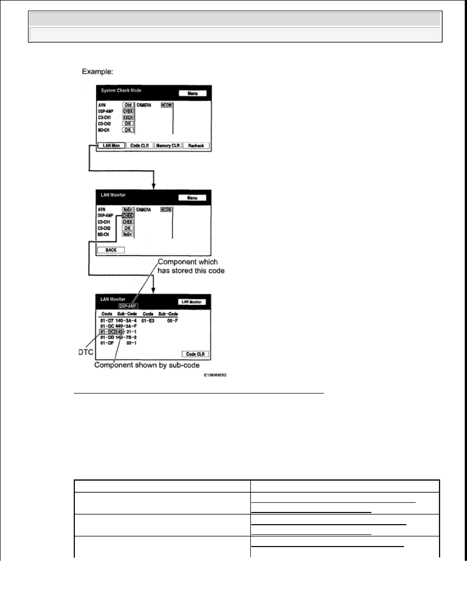
Fig. 305: Diagnostic Menu Screen Display - LAN Monitor Mode 
Courtesy of TOYOTA MOTOR SALES, U.S.A., INC. 

3. CHECK COMPONENT WHICH HAS STORED THIS CODE 

a. Select the component which has stored this code. 

Component table  

COMPONENT CHART 

Component

Proceed to

Navigation receiver (AVN)

NAVIGATION RECEIVER ASSEMBLY 
COMMUNICATION ERROR

Stereo component amplifier (DSP-AMP)

STEREO COMPONENT AMPLIFIER 
COMMUNICATION ERROR

Television display (Rr-TV)*

TELEVISION DISPLAY ASSEMBLY 


2009 Toyota Tundra 

2009 ACCESSORIES AND EQUIPMENT Navigation - Tundra


NEXT: END  

4. CLEAR DTC 

a. Clear the DTCs (see DTC CHECK/CLEAR ). 

HINT: 

If "01-DC" is output for only one component, this may not indicate a malfunction. 

5. RECHECK DTC 

a. Recheck for DTCs and check if the same trouble occurs again. 

OK: Malfunction disappears.  

NG: Go to step 6  

OK: USE SIMULATION METHOD TO CHECK (See ELECTRONIC CIRCUIT INSPECTION 
PROCEDURE
 ) 

6. CHECK COMPONENT WHICH HAS STORED THIS CODE 

a. Select the component which has stored this code. 

Component table  

COMPONENT CHART 

NEXT: END  

DTC 01-DD MASTER RESET; DTC 01-E1 VOICE PROCESSING DEVICE ON ERROR 

DESCRIPTION 

COMMUNICATION ERROR

HINT: 
*: w/ Rear Seat Entertainment System

Component

Proceed to

Navigation receiver (AVN)

STEREO COMPONENT AMPLIFIER 
COMMUNICATION ERROR

Stereo component amplifier (DSP-AMP)

NAVIGATION RECEIVER ASSEMBLY 
COMMUNICATION ERROR

Television display (Rr-TV)*

TELEVISION DISPLAY ASSEMBLY 
COMMUNICATION ERROR

HINT: 
*: w/ Rear Seat Entertainment System


2009 Toyota Tundra 

2009 ACCESSORIES AND EQUIPMENT Navigation - Tundra


DTC TROUBLE DETECTION CONDITION CHART 

INSPECTION PROCEDURE 

1. CHECK NAVIGATION RECEIVER POWER SOURCE CIRCUIT 

a. Refer to the NAVIGATION RECEIVER POWER SOURCE CIRCUIT . 

If the power source circuit is operating normally, proceed to the next step. 

2. INSPECT NAVIGATION RECEIVER 

a. Disconnect the K18 and K8 receiver connectors.  

b. Measure the resistance according to the value(s) in the table below. 

Standard resistance  

NAVIGATION RECEIVER TESTER CONNECTION SPECIFIED CONDITION 

DTC 

Code

DTC Detection Condition

Trouble Area

01-

DD*1

Device that should be master has been 
disconnected after engine starts.

Navigation receiver power source circuit  

AVC-LAN circuit between Navigation 
receiver and component which has stored 
this code  

Navigation receiver  

Component which has stored this code  

01-

E1*1, 

*2

Amplifier device records that amplifier output 
does not function even while source device is 
operating.

HINT: 

*1: This code may be stored if the engine is started, idled for 60 seconds and then the ignition 
switch is turned to the START position again.  

*2: Even if no fault is present, this trouble code may be stored depending on the battery condition 
or engine start voltage.  

NOTE:

Before starting troubleshooting, be sure to clear DTCs to erase codes 
stored due to the reasons described in the HINT above. Then, check for 
DTCs and troubleshoot according to the output DTCs.  

The navigation receiver is the master unit.  

Be sure to clear and recheck DTCs after the inspection is completed to 
confirm that no DTCs are output.  

NOTE:

Be sure to read the DESCRIPTION before performing the following procedures.

Tester Connection

Condition Specified Condition

K18-5(ATX+) - K18-15 (ATX-)

Always

60 to 80 ohms

K8-9 (TXM+) - K8-10 (TXM-)*

HINT: 


2009 Toyota Tundra 

2009 ACCESSORIES AND EQUIPMENT Navigation - Tundra


Fig. 306: Identifying K18 And K8 Receiver Connectors 
Courtesy of TOYOTA MOTOR SALES, U.S.A., INC. 

Result  

NAVIGATION RECEIVER RESULT CHART 

B: REPLACE NAVIGATION RECEIVER (see REMOVAL (For Column Shift Type) ) 

C: REPLACE NAVIGATION RECEIVER (see REMOVAL (For Floor Shift Type) ) 

A: Go to Next Step  

3. IDENTIFY COMPONENT WHICH HAS STORED THIS CODE 

a. Enter the diagnostic mode.  

b. Press the "LAN Mon" switch to change to "LAN Monitor" mode.  

c. Identify the component which has stored this code. 

Component table  

*: w/ Rear Seat Entertainment System

Result

Proceed to

OK

A

NG (for Column Shift Type)

B

NG (for Floor Shift Type)

C


2009 Toyota Tundra 

2009 ACCESSORIES AND EQUIPMENT Navigation - Tundra


Content   ..  542  543  544  545   ..