Toyota Tundra. Manual - part 514
 

  Index      Toyota     Toyota Tundra (2007-2010 year) - Service and Repair Manual


Search            copyright infringement  


Content   ..  512  513  514  515   ..


Toyota Tundra. Manual - part 514


NG: REPAIR OR REPLACE HARNESS OR CONNECTOR  

OK: PROCEED TO NEXT CIRCUIT INSPECTION SHOWN IN PROBLEM SYMPTOMS 
TABLE
  

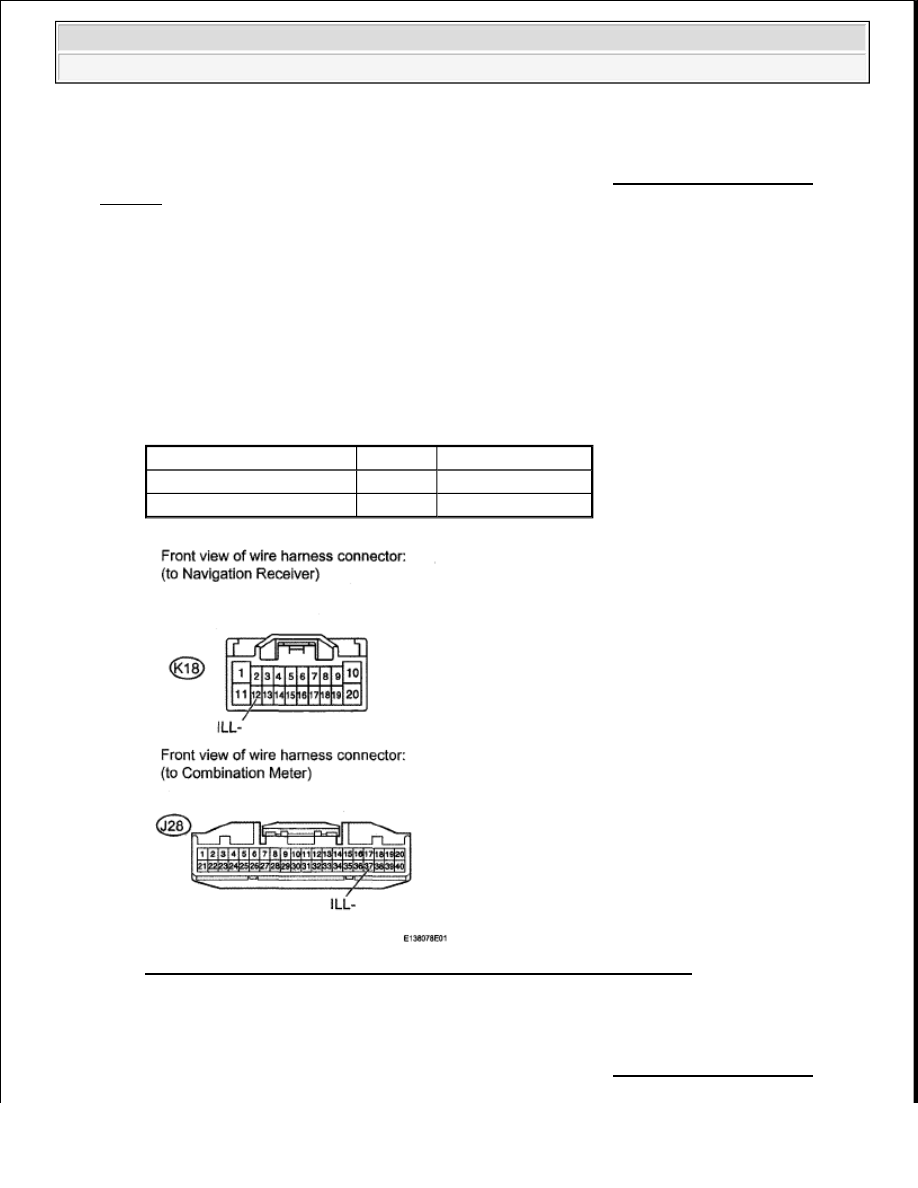
6. CHECK HARNESS AND CONNECTOR (NAVIGATION RECEIVER - COMBINATION 

METER) 

a. Disconnect the K18 display connector.  

b. Disconnect the J28 meter connector.  

c. Measure the resistance according to the value(s) in the table below. 

Standard resistance  

HARNESS AND CONNECTOR (NAVIGATION RECEIVER - COMBINATION METER) 
TESTER CONNECTION SPECIFIED CONDITION
 

Fig. 181: Identifying K18 Display Connector And J28 Meter Connector 
Courtesy of TOYOTA MOTOR SALES, U.S.A., INC. 

NG: REPAIR OR REPLACE HARNESS OR CONNECTOR  

OK: PROCEED TO NEXT CIRCUIT INSPECTION SHOWN IN PROBLEM SYMPTOMS 

Tester Connection

Condition Specified Condition

K18-12(ILL-)-J28-37 (ILL-) Always

Below 1 ohms

K18-12(ILL-)-Body ground

Always

10 kohms or higher


2009 Toyota Tundra 

2009 ACCESSORIES AND EQUIPMENT Navigation - Tundra


TABLE  

SPEAKER CIRCUIT 

DESCRIPTION 

The stereo component amplifier sends sound signals to the speaker. 

WIRING DIAGRAM 

Fig. 182: Speaker Circuit - Wiring Diagram (1 Of 2) 
Courtesy of TOYOTA MOTOR SALES, U.S.A., INC. 


2009 Toyota Tundra 

2009 ACCESSORIES AND EQUIPMENT Navigation - Tundra


Fig. 183: Speaker Circuit - Wiring Diagram (2 Of 2) 
Courtesy of TOYOTA MOTOR SALES, U.S.A., INC. 

INSPECTION PROCEDURE 

1. CHECK SPEAKER 

a. Check the malfunctioning speakers. 

Result  

SPEAKER RESULT CHART 

B: Go to step 11 

Result

Proceed to

Malfunction in front speaker area

A

Malfunction in rear speaker area

B


2009 Toyota Tundra 

2009 ACCESSORIES AND EQUIPMENT Navigation - Tundra


A: Go to Next Step  

2. CHECK SPEAKER 

a. Check the malfunctioning speakers. 

Result  

SPEAKER RESULT CHART 

B: Go to step 5 

C: Go to step 7 

D: Go to step 9 

A: Go to Next Step  

3. INSPECT FRONT NO. 1 SPEAKER 

a. Disconnect the M8 and N10 speaker connectors.  

b. Measure the resistance according to the value(s) in the table below. 

Standard resistance  

FRONT NO. 1 SPEAKER TESTER CONNECTION SPECIFIED CONDITION 

Fig. 184: Identifying M8 And N10 Speaker Connectors 
Courtesy of TOYOTA MOTOR SALES, U.S.A., INC. 

Result

Proceed to

Front No. 1 speaker

A

Front No. 2 speaker

B

Front No. 3 speaker

C

Front No. 4 speaker

D

Tester Connection Condition Specified Condition

1 - 2

Always

1.5 to 2.1 ohms


2009 Toyota Tundra 

2009 ACCESSORIES AND EQUIPMENT Navigation - Tundra


Content   ..  512  513  514  515   ..