Toyota Tundra. Manual - part 416
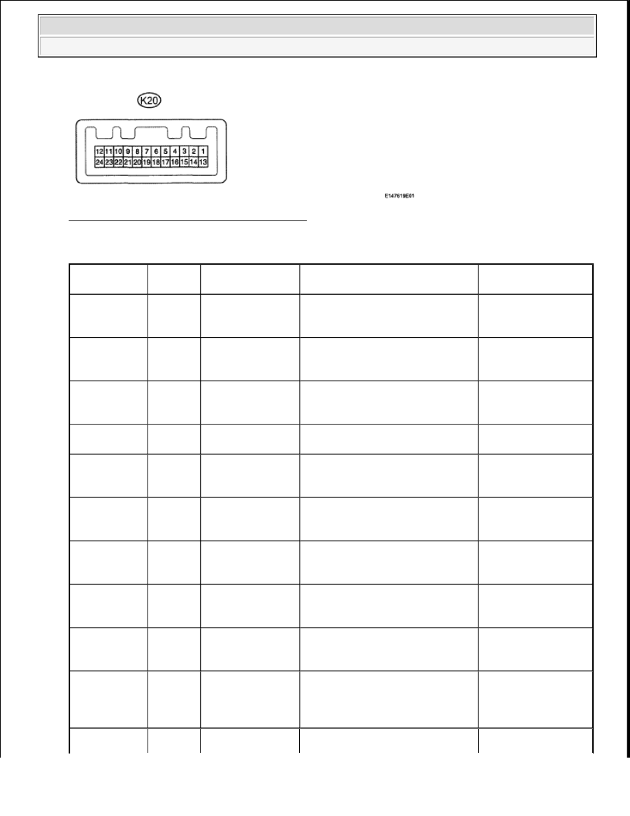
Fig. 19: Identifying K20 Connector Terminal
Courtesy of TOYOTA MOTOR SALES, U.S.A., INC.
K20 CONNECTOR TERMINAL VOLTAGE SPECIFICATIONS
Terminal No.
(Symbols)
Wiring
Color
Terminal
Description
Condition
Specified Condition
K20-3* (RR) -
Body ground
W - Body
ground
Ultrasonic sensor
(for rear corner
RH)
Clearance warning indicator LED
for rear corner RH illuminates
Below 3 V
K20-4* (FR) -
Body ground
Y - Body
ground
Ultrasonic sensor
(for front corner
RH)
Clearance warning indicator LED
for front corner RH illuminates
Below 3 V
K20-5* (BK) -
Body ground
O - Body
ground
Ultrasonic sensor
(for rear corner LH
and RH)
Clearance warning indicator LED
for back right and left sensor
illuminates
Below 3 V
K20-6* (OP) -
Body ground
P - Body
ground
Clearance warning
ECU signal
Clearance warning indicator's
operation indicator illuminates
Below 3 V
K20-7* (RL) -
Body ground
GR -
Body
ground
Ultrasonic sensor
(for rear corner
LH)
Clearance warning indicator LED
for rear corner LH illuminates
Below 3 V
K20-8* (FL) -
Body ground
LG -
Body
ground
Ultrasonic sensor
(for front corner
LH)
Clearance warning indicator LED
for front corner LH illuminates
Below 3 V
K20-10* (TX-
) - Body
ground
V - Body
ground
Cruise information
signal
Cruise information displays
Communication
signal
K20-11* (BZ)
- Body ground
L - Body
ground
Clearance warning
buzzer
Clearance warning buzzer
sounding (when the back sonar or
clearance sonar senses something)
Pulse generation
K20-12 (E)-
Body ground
W-B -
Body
ground
ECU ground
Always
Below 1 ohms
K20-16
(MHTR) -
Body ground
BR -
Body
ground
Security indicator
signal
Security indicator illuminates
(illuminates only for 60 sec. in
alarm sounding states (blinks when
system is in armed state))
3 to 5V
Alternating between
2009 Toyota Tundra
2009 ACCESSORIES AND EQUIPMENT Meter - Tundra