Toyota Tundra. Manual - part 304
 

  Index      Toyota     Toyota Tundra (2007-2010 year) - Service and Repair Manual


Search            copyright infringement  


Content   ..  302  303  304  305   ..


Toyota Tundra. Manual - part 304


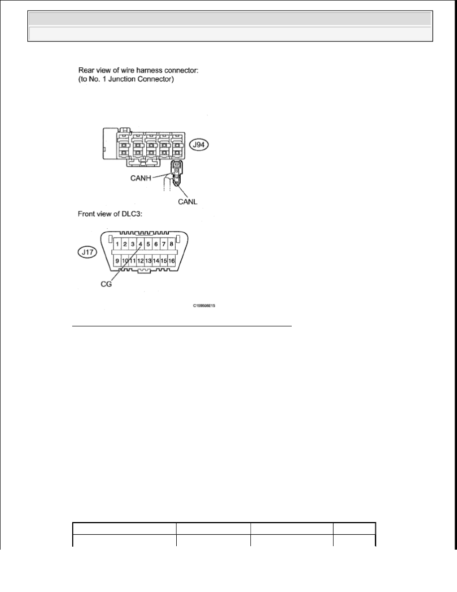
Fig. 139: Identifying J17 & J94 No. 1 Junction Connector 
Courtesy of TOYOTA MOTOR SALES, U.S.A., INC. 

NG: REPAIR OR REPLACE CAN MAIN WIRE OR CONNECTOR (NO. 1 JUNCTION 
CONNECTOR - NO. 2 JUNCTION CONNECTOR)
  

OK: Go to next step  

6. CONNECT CONNECTOR 

a. Reconnect the J94 No. 1 junction connector connector.  

b. Reconnect the J93 No. 2 junction connector connector.  

7. CHECK FOR SHORT TO GND IN CAN BUS WIRE (NO. 1 JUNCTION CONNECTOR - 

COMBINATION METER ECU) 

a. Disconnect the J84 No. 1 junction connector connector.  

b. Measure the resistance according to the value(s) in the table below. 

Result  

RESULT REFERENCE TABLE 

Tester Connection

Switch Condition Measured Resistance Proceed to


2009 Toyota Tundra 

2009 ACCESSORIES & EQUIPMENT CAN Communication - Tundra


Fig. 140: Identifying J84 No. 1 Junction And J17 Connector Terminals 
Courtesy of TOYOTA MOTOR SALES, U.S.A., INC. 

NG: Go to step 12 

OK: Go to next step  

8. CHECK FOR SHORT TO GND IN CAN BUS WIRE (NO. 1 JUNCTION CONNECTOR - MAIN 

BODY ECU) 

a. Disconnect the J96 No. 1 junction connector connector.  

b. Measure the resistance according to the value(s) in the table below. 

Result  

RESULT REFERENCE TABLE 

J84-1 (CANH) - J17-4 (CG)

Ignition switch OFF

1 ohms or higher

OK

J84-2 (CANL) - J17-4 (CG)

J84-1 (CANH) - J17-4 (CG)

Ignition switch OFF

Below 1 ohms

NG

J84-2 (CANL) - J17-4 (CG)

Tester Connection

Switch Condition Measured Resistance Proceed to


2009 Toyota Tundra 

2009 ACCESSORIES & EQUIPMENT CAN Communication - Tundra


Fig. 141: Identifying J96 No. 1 Junction And J17 Connector Terminals 
Courtesy of TOYOTA MOTOR SALES, U.S.A., INC. 

NG: Go to step 13 

OK: Go to next step  

9. CHECK FOR SHORT TO GND IN CAN BUS WIRE (NO. 1 JUNCTION CONNECTOR - SKID 

CONTROL ECU WITH ACTUATOR) 

a. Disconnect the A46 No. 1 junction connector connector.  

b. Measure the resistance according to the value(s) in the table below. 

Result  

RESULT REFERENCE TABLE 

J96-1 (CANH) - J17-4 (CG)

Ignition switch OFF

1 ohms or higher

OK

J96-2 (CANL) - J17-4 (CG)

J96-1 (CANH) - J17-4 (CG)

Ignition switch OFF

Below 1 ohms

NG

J96-2 (CANL) - J17-4 (CG)

Tester Connection

Switch Condition Measured Resistance Proceed to


2009 Toyota Tundra 

2009 ACCESSORIES & EQUIPMENT CAN Communication - Tundra


Fig. 142: Identifying A46 No. 1 Junction And J17 Connector Terminals 
Courtesy of TOYOTA MOTOR SALES, U.S.A., INC. 

NG: Go to step 14 

OK: Go to next step  

10. CHECK FOR SHORT TO GND IN CAN BUS WIRE (NO. 1 JUNCTION CONNECTOR - 

STEERING ANGLE SENSOR) 

a. Disconnect the J87 No. 1 junction connector connector.  

b. Measure the resistance according to the value(s) in the table below. 

Result  

RESULT REFERENCE TABLE 

A46-1 (CANH) - J17-4 (CG)

Ignition switch OFF

1 ohms or higher

OK

A46-2 (CANL) - J17-4 (CG)

A46-1 (CANH) - J17-4 (CG)

Ignition switch OFF

Below 1 ohms

NG

A46-2 (CANL) - J17-4 (CG)

Tester Connection

Switch Condition Measured Resistance Proceed to


2009 Toyota Tundra 

2009 ACCESSORIES & EQUIPMENT CAN Communication - Tundra


Content   ..  302  303  304  305   ..