Toyota Tundra. Manual - part 2932


  Index      Toyota     Toyota Tundra (2007-2010 year) - Service and Repair Manual


Search            copyright infringement  


Content   ..  2930  2931  2932  2933   ..


Toyota Tundra. Manual - part 2932
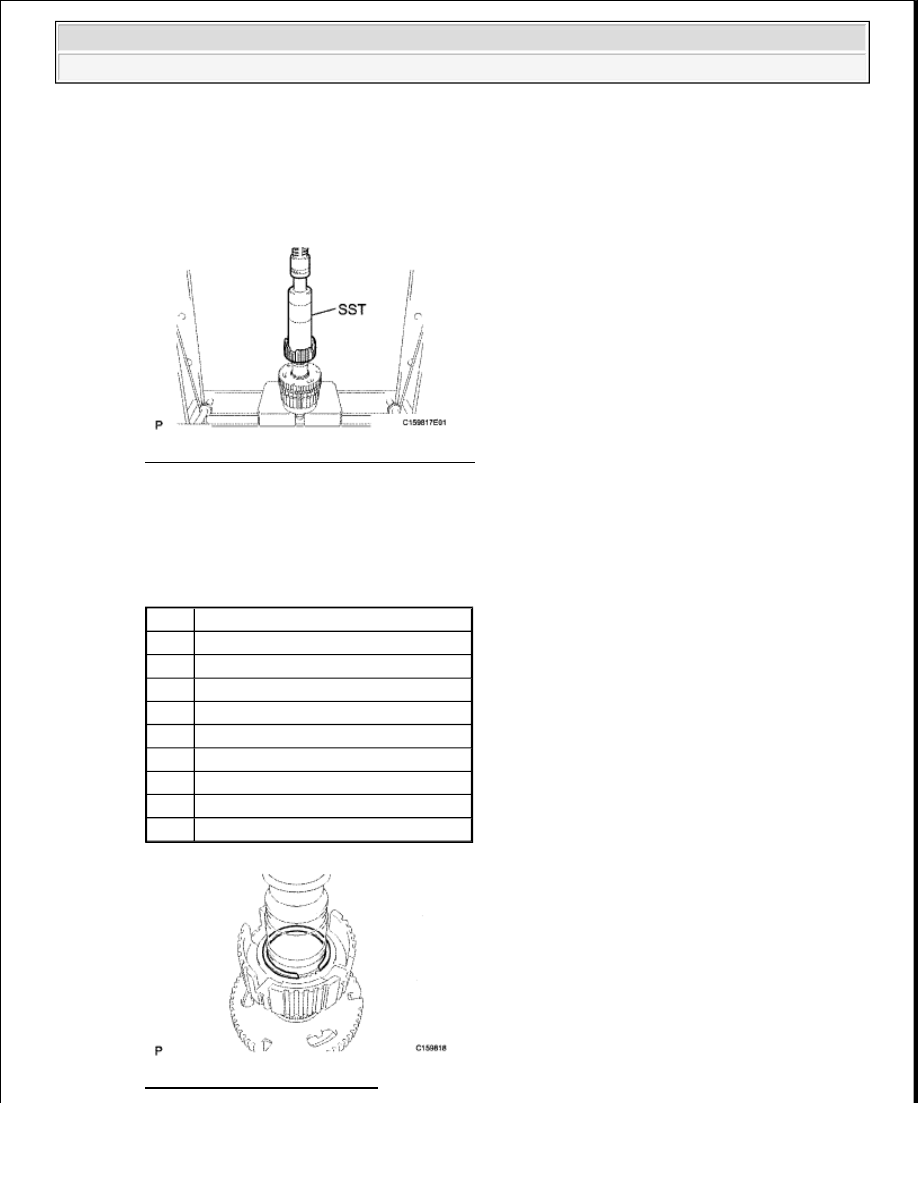


7. INSTALL TRANSFER CLUTCH HUB 

a. Using SST and a press, press in the clutch hub. 

SST 09316-60011 (09316-00011)  

Fig. 76: Pressing In Clutch Hub Using SST 
Courtesy of TOYOTA MOTOR SALES, U.S.A., INC. 

b. Select a snap ring that allows for minimum axial play and install it to the shaft. 

Snap ring thickness  

SNAP RING THICKNESS 

Fig. 77: Identifying Snap Ring 

Mark

Thickness

B

2.12 to 2.17 mm (0.0835 to 0.0854 in.

C

2.17 to 2.22 mm (0.0854 to 0.0874 in.

D

2.22 to 2.27 mm (0.0874 to 0.0894 in.

E

2.27 to 2.32 mm (0.0894 to 0.0913 in.

F

2.32 to 2.37 mm (0.0913 to 0.0933 in.

G

2.37 to 2.42 mm (0.0933 to 0.0953 in.

H

2.42 to 2.47 mm (0.0953 to 0.0974 in.

J

2.47 to 2.52 mm (0.0974 to 0.0992 in.

K

2.52 to 2.57 mm (0.0992 to 0.101 in.)


2009 Toyota Tundra 

2009 TRANSMISSION JF1A Transfer - Tundra


Courtesy of TOYOTA MOTOR SALES, U.S.A., INC. 

c. Using a snap ring expander, install the snap ring. 

8. INSTALL TRANSFER HIGH AND LOW CLUTCH SLEEVE 

a. Install the high and low clutch sleeve onto the clutch hub. 

Fig. 78: Identifying High And Low Clutch Sleeve 
Courtesy of TOYOTA MOTOR SALES, U.S.A., INC. 

9. INSTALL TRANSFER SYNCHROMESH SHIFTING KEY SPRING 

a. Install the synchromesh shifting key and synchromesh shifting key spring as shown in the 

illustration. 

Fig. 79: Identifying Synchromesh Shifting Key And Synchromesh Shifting Key Spring 
Courtesy of TOYOTA MOTOR SALES, U.S.A., INC. 

b. Using a snap ring expander, install the snap ring. 

NOTE:

Make sure that the snap ring is firmly installed to the groove.

NOTE:

Make sure that the high and low clutch sleeve is installed facing the 
correct direction.


2009 Toyota Tundra 

2009 TRANSMISSION JF1A Transfer - Tundra


Fig. 80: Identifying Snap Ring 
Courtesy of TOYOTA MOTOR SALES, U.S.A., INC. 

10. INSTALL NO. 1 TRANSFER OUTPUT SHAFT SPACER 

a. Install the washer, low planetary gear bearing and output shaft spacer to the output shaft. 

Fig. 81: Identifying Washer, Low Planetary Gear Bearing And Output Shaft Spacer 
Courtesy of TOYOTA MOTOR SALES, U.S.A., INC. 

b. Using a snap ring expander, install the snap ring. 

Fig. 82: Identifying Snap Ring 
Courtesy of TOYOTA MOTOR SALES, U.S.A., INC. 

NOTE:

Make sure that the snap ring is firmly installed to the groove.

NOTE:

Make sure that the snap ring is firmly installed to the groove.


2009 Toyota Tundra 

2009 TRANSMISSION JF1A Transfer - Tundra


11. INSTALL TRANSFER CASE FRONT OIL SEAL 

a. Using SST and a hammer, tap in a new oil seal until its surface is 1 to 1.5 mm (0.0394 to 0.0591 

in.) from the front case upper surface. 

SST 09950-60020 (09951-00720), 09950-70010 (09951-07100)  

Fig. 83: Tapping In Oil Seal Using SST 
Courtesy of TOYOTA MOTOR SALES, U.S.A., INC. 

b. Coat the lip of the oil seal with MP grease.  

12. INSTALL TRANSFER DRIVEN SPROCKET BEARING 

a. Install the bearing to the front case in the direction shown in the illustration. 

Fig. 84: Identifying Bearing Install Direction 
Courtesy of TOYOTA MOTOR SALES, U.S.A., INC. 

b. Using a screwdriver, install the snap ring. 

NOTE:

Be careful not to damage the front case.

NOTE:

Make sure the bearing is installed in the correct direction.


2009 Toyota Tundra 

2009 TRANSMISSION JF1A Transfer - Tundra


Content   ..  2930  2931  2932  2933   ..