Toyota Tundra. Manual - part 2793


  Index      Toyota     Toyota Tundra (2007-2010 year) - Service and Repair Manual


Search            copyright infringement  


Content   ..  2791  2792  2793  2794   ..


Toyota Tundra. Manual - part 2793
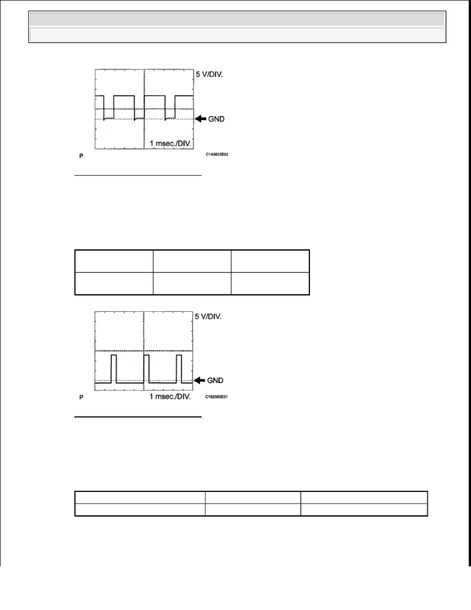


Fig. 12: Identifying Waveform 3 
Courtesy of TOYOTA MOTOR SALES, U.S.A., INC. 

d. Using an oscilloscope, check waveform 4. 

Reference:  

WAVEFORM REFERENCE TABLE 

Fig. 13: Identifying Waveform 4 
Courtesy of TOYOTA MOTOR SALES, U.S.A., INC. 

e. Using an oscilloscope, check waveform 5. 

Reference:  

WAVEFORM REFERENCE TABLE 

Terminal No. 

(Symbol)

Tool Setting

Condition

D74-10 (SLU+) - 
D74-11 (SLU-)

5 V/DIV., 1 

msec./DIV.

5th (lock-up)

Terminal No. (Symbol)

Tool Setting

Condition

D74-101 (SP2+) - D74-100 (SP2-) 2 V/DIV., 20 msec./DIV. Vehicle speed 20 km/h (12 MPH)


2009 Toyota Tundra 

2009 TRANSMISSION AB60F Automatic Transaxle - Tundra


Fig. 14: Identifying Waveform 5 
Courtesy of TOYOTA MOTOR SALES, U.S.A., INC. 

f. Using an oscilloscope, check waveform 6. 

Reference:  

WAVEFORM REFERENCE TABLE 

Fig. 15: Identifying Waveform 6 
Courtesy of TOYOTA MOTOR SALES, U.S.A., INC. 

g. Using an oscilloscope, check waveform 7. 

Reference:  

WAVEFORM REFERENCE TABLE 

Terminal No. (Symbol)

Tool Setting

Condition

D74-124 (NT+) - D74-123 (NT-) 1 V/DIV., 2 msec./DIV. Engine is idling (P or N position)

Terminal No. 

(Symbol)

Tool Setting

Condition

A24-10 (CANH) - 
D74-81 (E1)

1 V/DIV., 10 

µsec./DIV.

Ignition switch ON


2009 Toyota Tundra 

2009 TRANSMISSION AB60F Automatic Transaxle - Tundra


Fig. 16: Identifying Waveform 7 
Courtesy of TOYOTA MOTOR SALES, U.S.A., INC. 

h. Using an oscilloscope, check waveform 8. 

Reference:  

WAVEFORM REFERENCE TABLE 

Fig. 17: Identifying Waveform 8 
Courtesy of TOYOTA MOTOR SALES, U.S.A., INC. 

DIAGNOSIS SYSTEM 

1. DESCRIPTION 

a. When troubleshooting On-Board Diagnostic (OBD II) vehicles, the vehicle must be connected to 

the OBD II scan tool (complying with SAE J1987). Various data output from the vehicle's ECM 
can then be read.  

b. OBD II regulations require that the vehicle's onboard computer illuminate the Malfunction 

Indicator Lamp (MIL) on the instrument panel when the computer detects a malfunction in: 

1. The emission control system/components  

2. The powertrain control components (which affect vehicle emissions)  

Terminal No. 

(Symbol)

Tool Setting

Condition

A24-11 (CANL) - 
D74-81 (E1)

1 V/DIV., 10 

µsec./DIV.

Ignition switch ON


2009 Toyota Tundra 

2009 TRANSMISSION AB60F Automatic Transaxle - Tundra


3. The computer 

Fig. 18: Identifying Malfunction Indicator Lamp (MIL) 
Courtesy of TOYOTA MOTOR SALES, U.S.A., INC. 

In addition, the applicable Diagnostic Trouble Codes (DTCs) prescribed by SAE J2012 are 
recorded in the ECM memory. When the malfunction does not reoccur, the MIL stays 
illuminated until the ignition switch is turned off, and the MIL turns off when the engine is 
started. However, the DTCs remain recorded in the ECM memory. 

c. To check DTCs, connect the Techstream to the Data Link Connector 3 (DLC3) of the vehicle. The 

Techstream displays DTCs, the freeze frame data and a variety of the engine data. 

The DTCs and freeze frame data can be erased with the Techstream (see DTC CHECK/CLEAR ). 

2. NORMAL MODE AND CHECK MODE 

a. The diagnosis system operates in "normal mode" during normal vehicle use. In normal mode, "2 

trip detection logic" is used to ensure accurate detection of malfunctions. "Check mode" is also 
available to technicians as an option. In check mode, "1 trip detection logic" is used for simulating 
malfunction symptoms and increasing the system's ability to detect malfunctions, including 
intermittent malfunctions.  

3. 2 TRIP DETECTION LOGIC 

a. When a malfunction is first detected, the malfunction is temporarily stored in the ECM memory 

(1st trip). If the same malfunction is detected during the next drive cycle, the MIL is illuminated 
(2nd trip).  

4. FREEZE FRAME DATA 

a. Freeze frame data records the engine conditions (fuel system, calculated load, engine coolant 

temperature, fuel trim, engine speed, vehicle speed, etc.) when a malfunction is detected. When 
troubleshooting, freeze frame data can help determine if the vehicle was moving or stationary, if the 
engine was warmed up or not, if the air-fuel ratio was lean or rich, and other data from the time the 
malfunction occurred.  

b. The ECM records freeze frame data at 5 different times: 1) 3 times before the DTC is set, 2) once 

when the DTC is set, and 3) once after the DTC is set. These data can be used to simulate the 
vehicle's condition around the time when the malfunction occurred. The data may help find the 
cause of the malfunction, or judge if the DTC is being caused by a temporary malfunction or not. 


2009 Toyota Tundra 

2009 TRANSMISSION AB60F Automatic Transaxle - Tundra


Content   ..  2791  2792  2793  2794   ..