Toyota Tundra. Manual - part 2596


  Index      Toyota     Toyota Tundra (2007-2010 year) - Service and Repair Manual


Search            copyright infringement  


Content   ..  2594  2595  2596  2597   ..


Toyota Tundra. Manual - part 2596
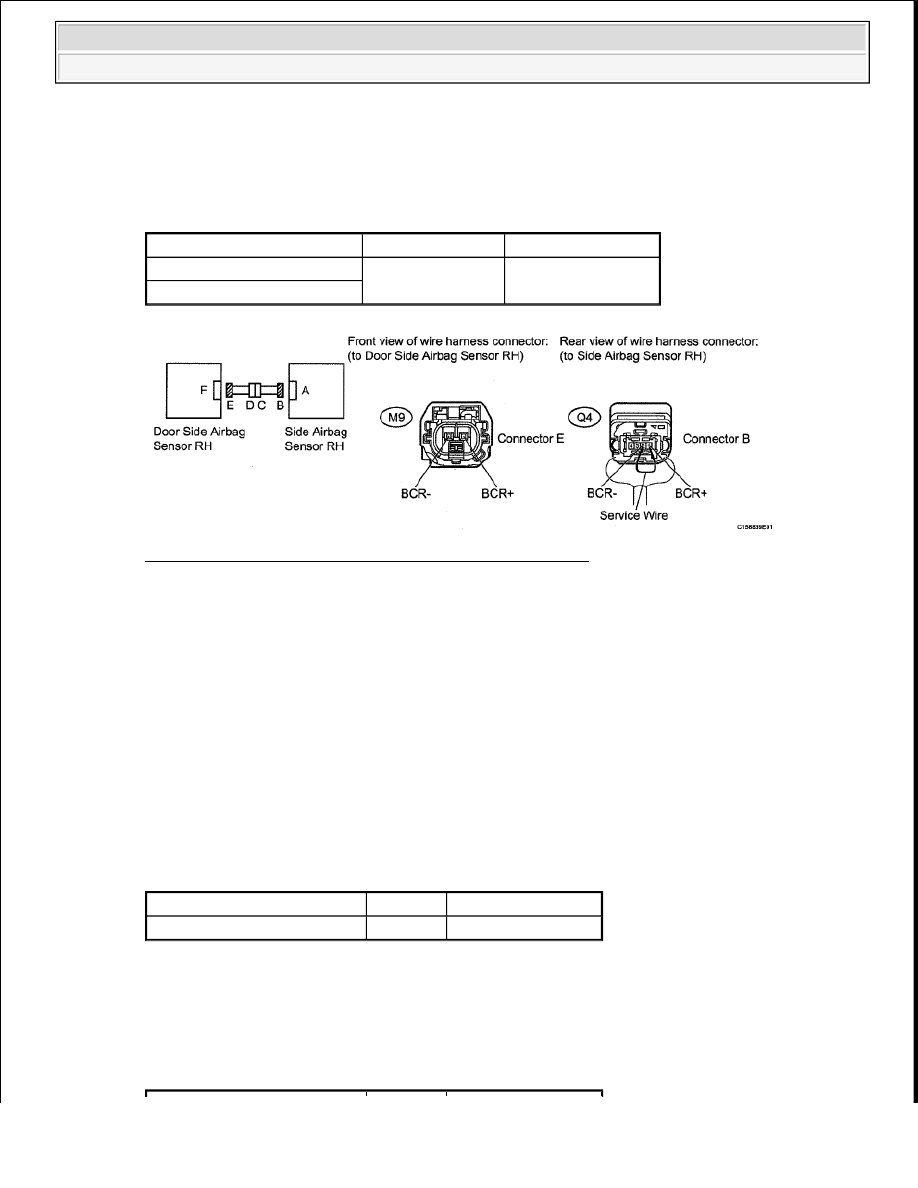


c. Measure the voltage according to the value(s) in the table below. 

Standard voltage  

TESTER CONNECTION SPECIFIED CONDITION TABLE 

Fig. 132: Identifying Door Side Airbag Sensor RH Circuit 
Courtesy of TOYOTA MOTOR SALES, U.S.A., INC. 

d. Turn the ignition switch OFF.  

e. Disconnect the negative (-) terminal cable from the battery, and wait for at least 90 seconds.  

f. Disconnect the connectors from the side airbag sensor RH and door side airbag sensor RH.  

g. Using a service wire, connect terminals 1 (BCR+) and 2 (BCR-) of connector B. 

h. Measure the resistance according to the value(s) in the table below. 

Standard Resistance  

TESTER CONNECTION SPECIFIED CONDITION TABLE 

i. Disconnect the service wire from the connector B.  

j. Measure the resistance according to the value(s) in the table below. 

Standard Resistance  

TESTER CONNECTION SPECIFIED CONDITION TABLE 

Tester Connection

Switch Condition Specified Condition

M9-1 (BCR-) - Body ground

Ignition switch ON

Below 1 V

M9-2 (BCR+) - Body ground

NOTE:

Do not forcibly insert a service wire into the terminals of the 
connector when connecting the wire.

Tester Connection

Condition Specified Condition

M9-1 (BCR-) - M9-2 (BCR+) Always

Below 1 ohms


2009 Toyota Tundra 

2009 RESTRAINTS Supplemental Restraint System - Tundra


Result  

RESULT TABLE 

A: Go to step 8 

B: Go to step 7 

C: Go to next step  

5. CHECK DOOR SIDE AIRBAG SENSOR RH 

a. Interchange the door side airbag sensor LH with RH and connect the connectors to them.  

b. Connect the negative (-) terminal to the battery, and wait for at least 2 seconds.  

c. Turn the ignition switch ON, and wait for at least 60 seconds.  

d. Clear the DTCs stored in the memory (see DTC CHECK/CLEAR ).  

e. Turn the ignition switch OFF.  

f. Turn the ignition switch ON, and wait for at least 60 seconds.  

g. Check for DTCs (see DTC CHECK/CLEAR ). 

Fig. 133: Identifying Door Side Airbag Sensor RH 
Courtesy of TOYOTA MOTOR SALES, U.S.A., INC. 

Result  

RESULT TABLE 

Tester Connection

Condition Specified Condition

M9-1 (BCR-) - M9-2 (BCR+)

Always

1 Mohms or higher

M9-1 (BCR-) - Body ground

M9-2 (BCR+) - Body ground

Result

Proceed to

OK (for CrewMax)

A

NG

B

OK (for Regular Cab and Double Cab)

C

Result

Proceed to


2009 Toyota Tundra 

2009 RESTRAINTS Supplemental Restraint System - Tundra


h. Turn the ignition switch OFF.  

i. Disconnect the negative (-) terminal cable from the battery, and wait for at least 90 seconds.  

j. Return the door side airbag sensor RH and LH to their original positions and connect the 

connectors to them.  

A: REPLACE DOOR SIDE AIRBAG SENSOR RH (See SIDE AIRBAG SENSOR (for Regular 
Cab)
 ) 

B: REPLACE DOOR SIDE AIRBAG SENSOR RH (See SIDE AIRBAG SENSOR (for Double 
Cab)
 ) 

C: USE SIMULATION METHOD TO CHECK (See DIAGNOSIS SYSTEM ) 

D: Go to next step  

6. CHECK SIDE AIRBAG SENSOR RH 

a. Interchange the side airbag sensor LH with RH and connect the connectors to them.  

b. Connect the negative (-) terminal to the battery, and wait for at least 2 seconds.  

c. Turn the ignition switch ON, and wait for at least 60 seconds.  

d. Clear the DTCs stored in the memory (see DTC CHECK/CLEAR ).  

e. Turn the ignition switch OFF.  

f. Turn the ignition switch ON, and wait for at least 60 seconds.  

g. Check for DTCs (see DTC CHECK/CLEAR ). 

Fig. 134: Identifying Side Airbag Sensor RH 
Courtesy of TOYOTA MOTOR SALES, U.S.A., INC. 

Result  

RESULT TABLE 

DTC B1690 is output (for Regular Cab)

A

DTC B1690 is output (for Double Cab)

B

DTC B1690 and B1695 are not output

C

DTC B1695 is output

D


2009 Toyota Tundra 

2009 RESTRAINTS Supplemental Restraint System - Tundra


h. Turn the ignition switch OFF.  

i. Disconnect the negative (-) terminal cable from the battery, and wait for at least 90 seconds.  

j. Return the side airbag sensor RH and LH to their original positions and connect the connectors to 

them.  

A: USE SIMULATION METHOD TO CHECK (See DIAGNOSIS SYSTEM ) 

B: REPLACE SIDE AIRBAG SENSOR RH (See SIDE AIRBAG SENSOR (for Regular Cab) ) 

C: REPLACE SIDE AIRBAG SENSOR RH (See SIDE AIRBAG SENSOR (for Double Cab) ) 

D: REPLACE CENTER AIRBAG SENSOR ASSEMBLY (See CENTER AIRBAG SENSOR 
ASSEMBLY (for Column Shift Type)
 ) 

E: REPLACE CENTER AIRBAG SENSOR ASSEMBLY (See CENTER AIRBAG SENSOR 
ASSEMBLY (for Floor Shift Type)
 ) 

7. CHECK NO. 2 FLOOR WIRE 

a. Disconnect the No. 2 floor wire connector from the door wire RH.  

b. Connect the negative (-) terminal cable to the battery, and wait for at least 2 seconds.  

c. Turn the ignition switch ON.  

d. Measure the voltage according to the value(s) in the table below. 

Standard voltage  

TESTER CONNECTION SPECIFIED CONDITION TABLE 

e. Turn the ignition switch OFF.  

f. Disconnect the negative (-) terminal cable from the battery, and wait for at least 90 seconds.  

g. Using a service wire, connect terminals 1 (BCR+) and 2 (BCR-) of connector B. 

Result

Proceed to

DTC B1690 and B1695 are not output

A

DTC B1690 is output (for Regular Cab)

B

DTC B1690 is output (for Double Cab)

C

DTC B1695 is output (for Column Shift 
Type)

D

DTC B1695 is output (for Floor Shift Type)

E

Tester Connection

Switch Condition Specified Condition

MQ1-1 (BCR-) - Body ground

Ignition switch ON

Below 1 V

MQ1-2 (BCR+) - Body ground

NOTE:

Do not forcibly insert a service wire into the terminals of the 


2009 Toyota Tundra 

2009 RESTRAINTS Supplemental Restraint System - Tundra


Content   ..  2594  2595  2596  2597   ..