Toyota Tundra. Manual - part 2487


  Index      Toyota     Toyota Tundra (2007-2010 year) - Service and Repair Manual


Search            copyright infringement  


Content   ..  2485  2486  2487  2488   ..


Toyota Tundra. Manual - part 2487
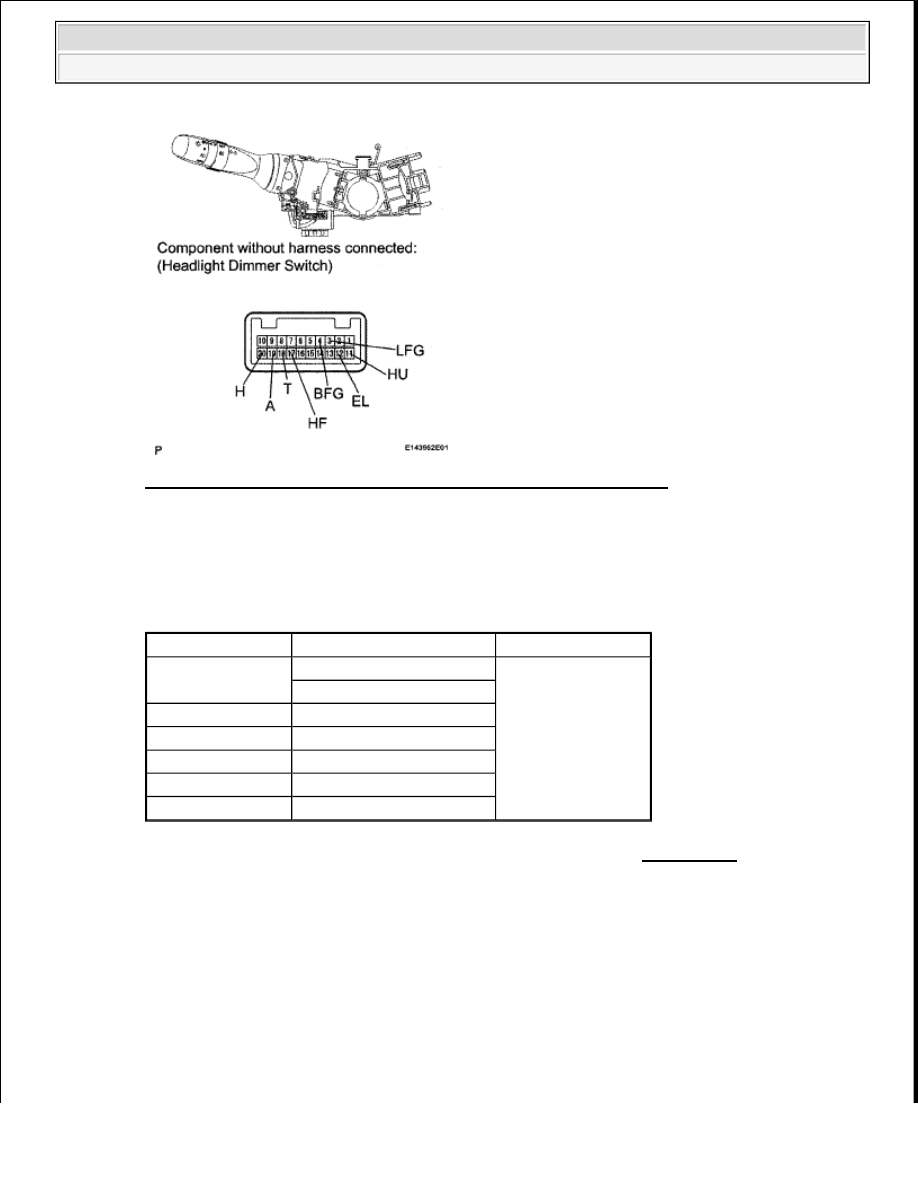


Fig. 56: Identifying Headlight Dimmer Switch Connector Terminals 
Courtesy of TOYOTA MOTOR SALES, U.S.A., INC. 

b. Measure the resistance according to the value(s) in the table below. 

Standard resistance  

HEADLIGHT DIMMER SWITCH ASSEMBLY 

NG: REPLACE HEADLIGHT DIMMER SWITCH ASSEMBLY (see REMOVAL ) 

OK: Go to next step  

3. CHECK HARNESS AND CONNECTOR (HEADLIGHT DIMMER SWITCH - MAIN BODY 

ECU AND BODY GROUND) 

Tester Connection

Switch Condition

Specified Condition

18 (T) - 12 (EL)

Light control switch Tail

Below 1 ohms

Light control switch HEAD

20 (H) - 12 (EL) Light control switch HEAD

19 (A) -12 (EL)

Light control switch AUTO

4 (BFG) - 3 (LFG) Front fog light switch ON

17 (HF) - 12 (EL)

Dimmer switch High

11 (HU) - 12 (EL)

Dimmer switch Low


2009 Toyota Tundra 

2009 ACCESSORIES AND EQUIPMENT Lighting - Tundra


Fig. 57: Identifying Headlight Dimmer Switch And Main Body ECU Connectors Terminals 
Courtesy of TOYOTA MOTOR SALES, U.S.A., INC. 

a. Disconnect the J10 switch connector.  

b. Disconnect the J3, J4 and DD ECU connectors.  

c. Measure the resistance according to the value(s) in the table below. 

Standard resistance  

HEADLIGHT DIMMER SWITCH - MAIN BODY ECU AND BODY GROUND 

Tester Connection

Condition Specified Condition

J10-4 (BFG) - J3-28 (FFOG)

Always

Below 1 ohms

J10-19 (A) - J4-21 (A)

J10-20 (H) - J3-17 (HEAD)

J10-18 (T) - J4-23 (TAIL)

J10-17 (HF) - J4-13 (HF)

J10-11 (HU) - DD-13 (HU)

J10-12 (EL) - Body ground

J10-3 (LFG) -Body ground

J10-4 (BFG) - Body ground

Always

10 kohms or higher

J10-19 (A) - Body ground
J10-20 (H) - Body ground

J10-18 (T) - Body ground

J10-17 (HF) - Body ground


2009 Toyota Tundra 

2009 ACCESSORIES AND EQUIPMENT Lighting - Tundra


NG: REPAIR OR REPLACE HARNESS OR CONNECTOR  

OK: REPLACE MAIN BODY ECU  

HEADLIGHT SIGNAL CIRCUIT 

DESCRIPTION 

The main body ECU receives a headlight Lo switch information signal from the light control switch, and 
illuminates the headlight low beam. 

WIRING DIAGRAM 

Fig. 58: Identifying Headlight Signal - Wiring Diagram 
Courtesy of TOYOTA MOTOR SALES, U.S.A., INC. 

INSPECTION PROCEDURE 

1. PERFORM ACTIVE TEST BY TECHSTREAM (HEADLIGHT) 

a. Operate the Techstream according to the steps on the display and select "Active Test". 

Techstream 

Main Body ECU  

J10-11 (HU) - Body ground


2009 Toyota Tundra 

2009 ACCESSORIES AND EQUIPMENT Lighting - Tundra


MAIN BODY ECU - TECHSTREAM ACTIVE TEST CHART 

OK: Headlight low beam turns on / turns off.  

NG: Go to step 2  

OK: PROCEED TO NEXT CIRCUIT INSPECTION SHOWN IN PROBLEM SYMPTOMS 
TABLE
  

2. INSPECT FUSE (HEAD LL, HEAD LR) 

a. Remove the HEAD LL and HEAD LR fuses from the engine room junction block.  

b. Measure the resistance according to the value(s) in the table below. 

Standard resistance  

FUSE (HEAD LL, HEAD LR) 

NG: REPLACE FUSE  

OK: Go to next step  

3. CHECK HARNESS AND CONNECTOR (HEADLIGHT LOW BULB - BATTERY) 

a. for LH: 

1. Disconnect the A10 headlight connector. 

Tester Display Test Part Control Range Diagnostic Note

Head Light

Headlight

ON or OFF

-

Tester Connection Condition Specified Condition

HEAD LL fuse

Always

Below 1 ohms

HEAD LR fuse


2009 Toyota Tundra 

2009 ACCESSORIES AND EQUIPMENT Lighting - Tundra


Content   ..  2485  2486  2487  2488   ..