Toyota Tundra. Manual - part 2431


  Index      Toyota     Toyota Tundra (2007-2010 year) - Service and Repair Manual


Search            copyright infringement  


Content   ..  2429  2430  2431  2432   ..


Toyota Tundra. Manual - part 2431
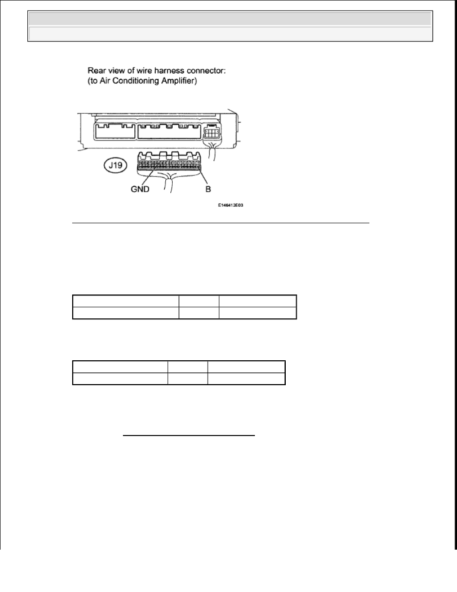


Fig. 143: Identifying Terminals Of J19 Air Conditioning Amplifier Connector 
Courtesy of TOYOTA MOTOR SALES, U.S.A., INC. 

b. Measure the resistance and voltage according to the value(s) in the table below. 

Standard Resistance  

TESTER CONNECTION SPECIFIED CONDITION CHART 

Standard Voltage  

TESTER CONNECTION SPECIFIED CONDITION CHART 

NG: REPAIR OR REPLACE HARNESS OR CONNECTOR  

OK: PROCEED TO NEXT CIRCUIT INSPECTION SHOWN IN PROBLEM SYMPTOMS 
TABLE
 (See PROBLEM SYMPTOMS TABLE ) 

IG POWER SOURCE CIRCUIT 

DESCRIPTION 

When the ignition switch is turned ON, positive (+) battery voltage is applied to the air conditioning amplifier. 

WIRING DIAGRAM 

Tester Connection

Condition Specified Condition

J19-14 (GND) -Body ground Always

Below 1 ohms

Tester Connection

Condition Specified Condition

J19-21 (B) - Body ground Always

11 to 14 V


2009 Toyota Tundra 

2009 HVAC Air Conditioning - Tundra


Fig. 144: IG Power Source - Wiring Diagram 
Courtesy of TOYOTA MOTOR SALES, U.S.A., INC. 

INSPECTION PROCEDURE 

1. INSPECT FUSE (ECU-IG NO. 1) 

a. Remove the ECU-IG No. 1 fuse from the main body ECU.  

b. Measure the resistance according to the value(s) in the table below. 

Standard Resistance  

TESTER CONNECTION SPECIFIED CONDITION CHART 

NG: REPLACE FUSE  

OK: Go to Next Step  

2. CHECK HARNESS AND CONNECTOR (AIR CONDITIONING AMPLIFIER - BATTERY AND 

BODY GROUND) 

a. Disconnect the J19 air conditioning amplifier connector. 

Tester Connection Condition Specified Condition

ECU-IG No. 1 fuse Always

Below 1 ohms


2009 Toyota Tundra 

2009 HVAC Air Conditioning - Tundra


Fig. 145: Identifying Terminals Of J19 Air Conditioning Amplifier Connector 
Courtesy of TOYOTA MOTOR SALES, U.S.A., INC. 

b. Measure the resistance and voltage according to the value(s) in the table below. 

Standard Resistance  

TESTER CONNECTION SPECIFIED CONDITION CHART 

Standard Voltage  

TESTER CONNECTION SPECIFIED CONDITION CHART 

NG: REPAIR OR REPLACE HARNESS OR CONNECTOR  

OK: PROCEED TO NEXT CIRCUIT INSPECTION SHOWN IN PROBLEM SYMPTOMS 
TABLE
 (See PROBLEM SYMPTOMS TABLE ) 

REFRIGERANT 

ON-VEHICLE INSPECTION 

1. INSPECT REFRIGERANT PRESSURE WITH MANIFOLD GAUGE SET 

a. This method uses a manifold gauge set to locate problem areas. Read the manifold gauge pressure 

when these conditions are established. 

Test conditions: 

Temperature at the air inlet is 30 to 35°C (86 to 95°F).  

Tester Connection

Condition Specified Condition

J19-14 (GND) - Body ground Always

Below 1 ohms

Tester Connection

Switch Condition Specified Condition

J19-1 (IG+) - Body ground Ignition switch ON

11 to 14 V


2009 Toyota Tundra 

2009 HVAC Air Conditioning - Tundra


Engine is running at 1500 RPM.  

All doors are fully open.  

Blower speed control switch is at HI.  

Air inlet control set at "RECIRC"  

A/C switch is ON.  

Gauge readings (Reference) 

Fig. 146: Refrigerant Pressure Graph 
Courtesy of TOYOTA MOTOR SALES, U.S.A., INC. 

1. Normally functioning refrigeration system 

Gauge reading  

REFRIGERATION SYSTEM PRESSURE REFERENCE 

Pressure side

Refrigerant volume

Low

0.15 to 0.25 MPa (1.5 to 2.5 kgf/cm

2

 )

High

1.37 to 1.57 MPa (14 to 16 kgf/cm

2

 )


2009 Toyota Tundra 

2009 HVAC Air Conditioning - Tundra


Content   ..  2429  2430  2431  2432   ..