Toyota Tundra. Manual - part 2272


  Index      Toyota     Toyota Tundra (2007-2010 year) - Service and Repair Manual


Search            copyright infringement  


Content   ..  2270  2271  2272  2273   ..


Toyota Tundra. Manual - part 2272


5. REMOVE V-RIBBED BELT TENSIONER ASSEMBLY (See REMOVAL )  

6. REMOVE NO. 2 IDLER PULLEY SUB-ASSEMBLY (See REMOVAL )  

7. REMOVE NO. 1 IDLER PULLEY SUB-ASSEMBLY (See REMOVAL )  

8. DISCONNECT NO. 2 OIL COOLER HOSE (See DISASSEMBLY )  

9. DISCONNECT OIL COOLER HOSE  

10. REMOVE WATER INLET HOUSING (See DISASSEMBLY )  

11. REMOVE VVT SENSOR (See REMOVAL )  

12. REMOVE CAMSHAFT TIMING OIL CONTROL VALVE ASSEMBLY (See DISASSEMBLY )  

13. REMOVE CYLINDER HEAD COVER SUB-ASSEMBLY RH (See DISASSEMBLY )  

14. REMOVE CYLINDER HEAD COVER SUB-ASSEMBLY LH (See DISASSEMBLY )  

15. REMOVE CRANKSHAFT PULLEY (See DISASSEMBLY )  

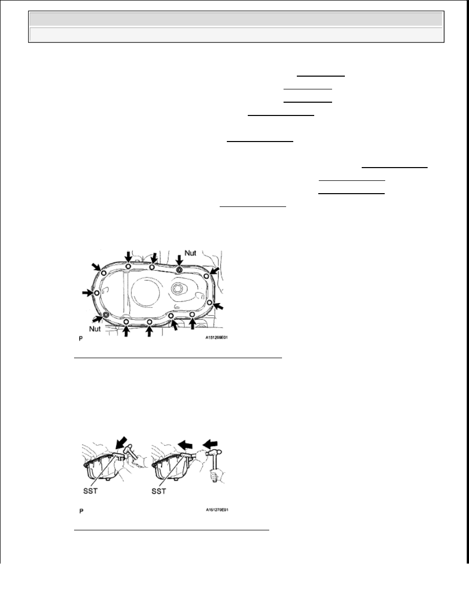
16. REMOVE NO. 2 OIL PAN SUB-ASSEMBLY 

a. Remove the 10 bolts and 2 nuts. 

Fig. 15: Identifying Engine Assembly Bolts And Nuts 
Courtesy of TOYOTA MOTOR SALES, U.S.A., INC. 

b. Insert the blade of SST between the oil pans. Cut through the applied sealer and remove the No. 2 

oil pan. 

SST 09032-00100  

Fig. 16: Inserting Blade Of SST Between Oil Pans 
Courtesy of TOYOTA MOTOR SALES, U.S.A., INC. 


2009 Toyota Tundra 

2009 ENGINE Lubrication (1GR-FE) - Tundra


17. REMOVE OIL STRAINER SUB-ASSEMBLY 

a. Remove the 2 nuts, oil strainer and gasket. 

Fig. 17: Identifying Oil Strainer Nuts 
Courtesy of TOYOTA MOTOR SALES, U.S.A., INC. 

18. REMOVE OIL PAN SUB-ASSEMBLY 

a. Remove the 17 bolts (A, B, C) and 2 nuts. 

Fig. 18: Identifying Oil Pan Sub-Assembly Bolts And Nuts 
Courtesy of TOYOTA MOTOR SALES, U.S.A., INC. 

b. Using a screwdriver, remove the oil pan by prying between the oil pan and cylinder block as shown 

in the illustration. 

NOTE:

Be careful not to damage the contact surfaces of the cylinder block 
and oil pan.


2009 Toyota Tundra 

2009 ENGINE Lubrication (1GR-FE) - Tundra


Fig. 19: Removing Oil Pan By Prying Between Oil Pan And Cylinder Block 
Courtesy of TOYOTA MOTOR SALES, U.S.A., INC. 

c. Remove the O-ring from the cylinder block.  

19. REMOVE OIL FILTER BRACKET SUB-ASSEMBLY (See DISASSEMBLY ) 

Fig. 20: Identifying O-Ring Onto Oil Pump 
Courtesy of TOYOTA MOTOR SALES, U.S.A., INC. 

20. REMOVE TIMING CHAIN COVER SUB-ASSEMBLY 

a. Remove the 24 bolts (A and B) and 2 nuts. 


2009 Toyota Tundra 

2009 ENGINE Lubrication (1GR-FE) - Tundra


Fig. 21: Identifying Timing Chain Cover Sub-Assembly Bolts And Nuts 
Courtesy of TOYOTA MOTOR SALES, U.S.A., INC. 

b. Remove the timing chain cover by prying between the timing chain cover and cylinder head or 

cylinder block with a screwdriver. 

Fig. 22: Identifying Timing Chain Cover By Prying Between Timing Chain Cover And 
Cylinder Head
 
Courtesy of TOYOTA MOTOR SALES, U.S.A., INC. 

c. Remove the O-ring from the cylinder head LH.  

21. REMOVE FRONT CRANKSHAFT OIL SEAL 

a. If the timing chain case is removed: 

NOTE:

Be careful not to damage the contact surfaces of the timing chain 
cover, cylinder block and cylinder head.


2009 Toyota Tundra 

2009 ENGINE Lubrication (1GR-FE) - Tundra


Content   ..  2270  2271  2272  2273   ..