Toyota Tundra. Manual - part 2250


  Index      Toyota     Toyota Tundra (2007-2010 year) - Service and Repair Manual


Search            copyright infringement  


Content   ..  2248  2249  2250  2251   ..


Toyota Tundra. Manual - part 2250
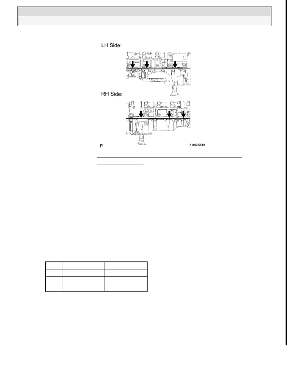


b. Install the heat exchanger cover with the 12 bolts and 2 nuts. 

Torque: for bolt C  

10 N*m (102 kgf*cm, 7 ft.*lbf)  

except bolt C  

21 N*m (214 kgf*cm, 16 ft.*lbf)  

Standard Bolt  

HEAT EXCHANGER COVER STANDARD BOLT REFERENCE CHART 

Fig. 340: Identifying Seal Packing Areas On No. 1 Heat 
Exchanger Cover 
Courtesy of TOYOTA MOTOR SALES, U.S.A., INC. 

Item

Length

Thread Diameter

Bolt A 20 mm (0.787 in.) 8 mm (0.315 in.)

Bolt B 70 mm (2.76 In.) 8 mm (0.315 In.)
Bolt C 16 mm (0.630 In.) 6 mm (0.236 In.)


2009 Toyota Tundra 

2009 ENGINE Engine Mechanical (3UR-FBE) - Tundra


Fig. 341: Locating Heat Exchanger Cover With Bolts And Nuts 
Courtesy of TOYOTA MOTOR SALES, U.S.A., INC. 

11. INSTALL VENTILATION PIPE GASKET 

a. Using SST, evenly tap in a new ventilation pipe gasket until its surface is flush with the lip of the 

ventilation pipe. 

SST 09950-60010 (09951 -00360), 09950-70010 (09951-07100)  

12. INSTALL CYLINDER BLOCK WATER JACKET SPACER 

a. Install the 2 water jacket spacers as shown in the illustration. 

NOTE:

Do not start the engine for at least 2 hours after installing.

NOTE:

Do not tap the gasket at an angle.  

Do not tap the gasket excessively. 

Fig. 342: Tapping In Ventilation Pipe Gasket 
Courtesy of TOYOTA MOTOR SALES, U.S.A., INC. 

NOTE:

Face the cutouts indicated by the arrows in illustration away 
from the engine.  

Face the "up mark" as shown in the illustration. 


2009 Toyota Tundra 

2009 ENGINE Engine Mechanical (3UR-FBE) - Tundra


13. INSTALL CYLINDER HEAD GASKET RH (See INSTALLATION )  

14. INSTALL CYLINDER HEAD GASKET LH (See INSTALLATION )  

15. INSTALL CYLINDER HEAD SUB-ASSEMBLY RH (See INSTALLATION )  

16. INSTALL CYLINDER HEAD SUB-ASSEMBLY LH (See INSTALLATION )  

17. INSTALL VALVE STEM CAP 

a. Apply a light coat of engine oil to the valve stem caps.  

b. Install the 32 valve stem caps to the cylinder head.  

18. INSTALL VALVE LASH ADJUSTER ASSEMBLY 

a. Inspect the valve lash adjuster (See INSPECTION ).  

b. Install the 32 valve lash adjusters to the cylinder head. 

19. INSTALL NO. 1 VALVE ROCKER ARM SUB-ASSEMBLY 

a. Apply engine oil to the lash adjuster tips and valve stem cap ends.  

b. Install the 32 valve rocker arms as shown in the illustration. 

Fig. 344: Identifying Valve Rocker Arms Position 

Fig. 343: Identifying Up Mark Position For Installing Cylinder 
Block Water Jacket Spacer 
Courtesy of TOYOTA MOTOR SALES, U.S.A., INC. 

NOTE:

Install the lash adjuster at the same place it was removed from.


2009 Toyota Tundra 

2009 ENGINE Engine Mechanical (3UR-FBE) - Tundra


Courtesy of TOYOTA MOTOR SALES, U.S.A., INC. 

20. INSTALL CAMSHAFT BEARING CAP RH 

a. Apply a light coat of engine oil to the camshaft journals, camshaft housings and bearing caps.  

b. Install the No. 1 and No. 2 camshafts to the camshaft housing.  

c. Confirm the marks and numbers on the camshaft bearing caps and place them in their proper 

positions and directions. 

Fig. 345: Identifying Camshaft Bearing Caps Sequence 
Courtesy of TOYOTA MOTOR SALES, U.S.A., INC. 

d. Temporarily install the 10 bolts in the order shown in the illustration. 

Fig. 346: Identifying Camshaft Bearing Cap Bolts Tightening Order 
Courtesy of TOYOTA MOTOR SALES, U.S.A., INC. 

21. INSTALL CAMSHAFT HOUSING SUB-ASSEMBLY RH 

a. Make sure that the valve rocker arms are installed as shown in the illustration. 


2009 Toyota Tundra 

2009 ENGINE Engine Mechanical (3UR-FBE) - Tundra


Content   ..  2248  2249  2250  2251   ..