Toyota Tundra. Manual - part 208
 

  Index      Toyota     Toyota Tundra (2007-2010 year) - Service and Repair Manual


Search            copyright infringement  


Content   ..  206  207  208  209   ..


Toyota Tundra. Manual - part 208


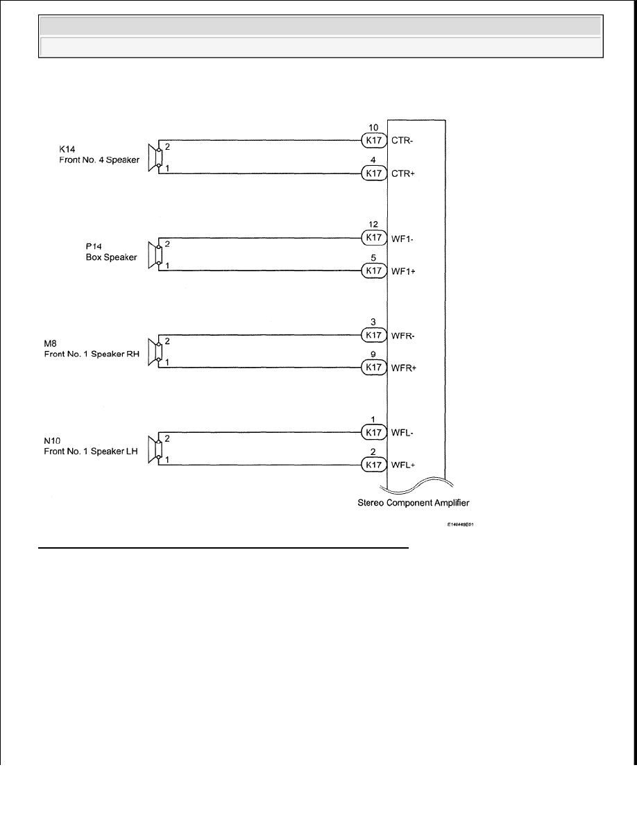
WIRING DIAGRAM 

Fig. 197: Speaker (Independent Amplifier) - Wiring Diagram (1 Of 2) 
Courtesy of TOYOTA MOTOR SALES, U.S.A., INC. 


2009 Toyota Tundra 

2009 ACCESSORIES AND EQUIPMENT Audio/Visual - Tundra


Fig. 198: Speaker (Independent Amplifier) - Wiring Diagram (2 Of 2) 
Courtesy of TOYOTA MOTOR SALES, U.S.A., INC. 

INSPECTION PROCEDURE 

1. CHECK SPEAKER 

a. Check the malfunctioning speakers. 

Result:  

RESULT REFERENCE 

B: Go to step 11 

Result

Proceed to

Malfunction in front speaker area

A

Malfunction in rear speaker area

B


2009 Toyota Tundra 

2009 ACCESSORIES AND EQUIPMENT Audio/Visual - Tundra


A: Go to next step.  

2. CHECK SPEAKER 

a. Check the malfunctioning speakers. 

Result:  

RESULT REFERENCE 

B: Go to step 5 

C: Go to step 7 

D: Go to step 9 

A: Go to next step.  

3. INSPECT FRONT NO. 1 SPEAKER 

a. Disconnect the M8 and N10 speaker connectors.  

b. Measure the resistance according to the value(s) in the table below. 

Standard resistance  

TESTER CONNECTION SPECIFIED CONDITION 

NG: REPLACE FRONT NO. 1 SPEAKER (see REMOVAL ) 

Fig. 199: Identifying Front No. 1 Speaker Connector Terminals 

Result

Proceed to

Front No. 1 speaker

A

Front No. 2 speaker

B

Front No. 3 speaker

C

Front No. 4 speaker

D

Tester Connection Condition Specified Condition

1 - 2

Always

1.5 to 2.1 ohms


2009 Toyota Tundra 

2009 ACCESSORIES AND EQUIPMENT Audio/Visual - Tundra


Courtesy of TOYOTA MOTOR SALES, U.S.A., INC. 

OK: Go to next step.  

4. CHECK HARNESS AND CONNECTOR (STEREO COMPONENT AMPLIFIER - FRONT NO. 1 

SPEAKER) 

a. Disconnect the M8 and N10 speaker connectors.  

b. Disconnect the K17 amplifier connector.  

c. Measure the resistance according to the value(s) in the table below. 

Standard resistance:  

for LH  

TESTER CONNECTION SPECIFIED CONDITION 

for RH  

TESTER CONNECTION SPECIFIED CONDITION 

Tester Connection

Condition Specified Condition

K17-2 (WFL+) - N10-1

Always

Below 1 ohms

K17-1 (WFL-)-N10-2

K17-2 (WFL+) - Body ground

Always

10 kohms or higher

K17-1 (WFL-) - Body ground

Tester Connection

Condition Specified Condition

K17-9 (WFR+) - M8-1

Always

Below 1 ohms

K17-3 (WFR-) - M8-2

K17-9 (WFR+) - Body ground

Always

10 kohms or higher

K17-3 (WFR-) - Body ground


2009 Toyota Tundra 

2009 ACCESSORIES AND EQUIPMENT Audio/Visual - Tundra


Content   ..  206  207  208  209   ..