Toyota Tundra. Manual - part 2076


  Index      Toyota     Toyota Tundra (2007-2010 year) - Service and Repair Manual


Search            copyright infringement  


Content   ..  2074  2075  2076  2077   ..


Toyota Tundra. Manual - part 2076
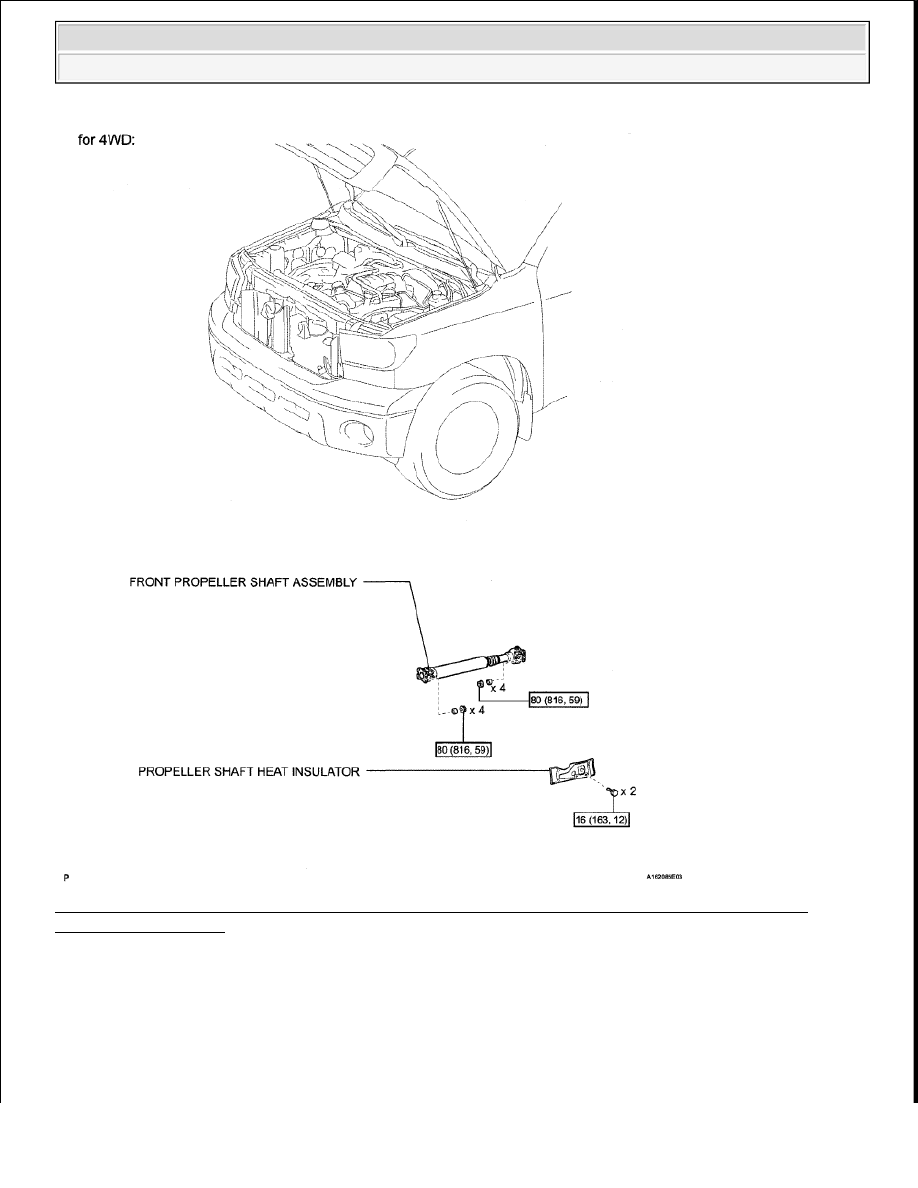


Fig. 27: Identifying Exhaust Pipe Components (Except Regular Cab Standard Deck) With Torque 
Specifications (1 Of 3)
 
Courtesy of TOYOTA MOTOR SALES, U.S.A., INC. 


2009 Toyota Tundra 

2009 ENG NE Exhaust (3UR-FE) - Tundra


Fig. 28: Identifying Exhaust Pipe Components (Except Regular Cab Standard Deck) With Torque 
Specifications (2 Of 3)
 
Courtesy of TOYOTA MOTOR SALES, U.S.A., INC. 


2009 Toyota Tundra 

2009 ENG NE Exhaust (3UR-FE) - Tundra


Fig. 29: Identifying Exhaust Pipe Components (Except Regular Cab Standard Deck) With Torque 
Specification (3 Of 3)
 
Courtesy of TOYOTA MOTOR SALES, U.S.A., INC. 

REMOVAL 


2009 Toyota Tundra 

2009 ENG NE Exhaust (3UR-FE) - Tundra


1

REMOVE TAILPIPE ASSEMBLY 

a

Remove the bolt, clamp and gasket   

b

Disconnect the tailpipe from the exhaust pipe support   

2

REMOVE CENTER EXHAUST PIPE ASSEMBLY 

a

Remove the 4 bolts   

b

Disconnect the center exhaust pipe from the 3 exhaust pipe supports   

c

Remove the center exhaust pipe from the front exhaust pipe and front No  2 exhaust pipe   

d

Remove the 2 gaskets from the front exhaust pipe   

3

REMOVE PROPELLER SHAFT HEAT INSULATOR (for 4WD) (see REMOVAL )  

4

REMOVE FRONT PROPELLER SHAFT ASSEMBLY (for 4WD) (See FRONT PROPELLER 
SHAFT ASSEMBLY
 )  

5

REMOVE FRONT NO. 2 EXHAUST PIPE ASSEMBLY 

a

Disconnect the air fuel ratio sensor connector   

b

Disconnect the heated oxygen sensor connector   

c

Remove the 3 nuts and the front No  2 exhaust pipe from the exhaust manifold LH   

d

Remove the gasket   

6

REMOVE FRONT EXHAUST PIPE ASSEMBLY 

a

Disconnect the air fuel ratio sensor connector   

b

Disconnect the heated oxygen sensor connector and 2 clamps   

c

Remove the 3 nuts and the front exhaust pipe from the exhaust manifold RH   

d

Remove the gasket   

7

REMOVE AIR FUEL RATIO SENSOR (for Bank 1 Sensor 1) (See REMOVAL )  

8

REMOVE AIR FUEL RATIO SENSOR (for Bank 2 Sensor 1) (See REMOVAL )  

9

REMOVE HEATED OXYGEN SENSOR (for Bank 1 Sensor 2) (See REMOVAL )  

10

REMOVE HEATED OXYGEN SENSOR (for Bank 2 Sensor 2) (See REMOVAL )  

INSTALLATION 

1

INSTALL AIR FUEL RATIO SENSOR (for Bank 1 Sensor 1) (See INSTALLATION )  

2

INSTALL AIR FUEL RATIO SENSOR (for Bank 2 Sensor 1) (See INSTALLATION )  

3

INSTALL HEATED OXYGEN SENSOR (for Bank 1 Sensor 2) (See INSTALLATION )  

4

INSTALL HEATED OXYGEN SENSOR (for Bank 2 Sensor 2) (See INSTALLATION )  

5

INSTALL FRONT EXHAUST PIPE ASSEMBLY 

a

Install a new gasket and the front exhaust pipe to the exhaust manifold RH with 3 new nuts  

CAUTION:

Wear protective gloves when removing the exhaust pipe.  

The exhaust pipe is extremely hot immediately after the engine has 
stopped.  

Confirm that the exhaust pipe has cooled down before removing it.  


2009 Toyota Tundra 

2009 ENG NE Exhaust (3UR-FE) - Tundra


Content   ..  2074  2075  2076  2077   ..