Toyota Tundra. Manual - part 2067


  Index      Toyota     Toyota Tundra (2007-2010 year) - Service and Repair Manual


Search            copyright infringement  


Content   ..  2065  2066  2067  2068   ..


Toyota Tundra. Manual - part 2067


b

Install a new gasket and the front No  2 exhaust pipe to the exhaust manifold LH with 3 new nuts  

Torque: 54 N*m (554 kgf*cm, 40 ft.*lbf)  

c

Install a new gasket and the front No  2 exhaust pipe to the center exhaust pipe with the 2 bolts  

Torque: 48 N*m (489 kgf*cm, 35 ft.*lbf)  

d

Connect the air fuel ratio sensor connector   

e

Connect the heated oxygen sensor connector   

8

INSTALL FRONT NO. 2 EXHAUST PIPE ASSEMBLY (for Regular Cab Standard Deck) 

a

Install a new gasket and the front No  2 exhaust pipe to the exhaust manifold LH with 3 new nuts  

Torque: 54 N*m (554 kgf*cm, 40 ft.*lbf)  

b

Install a new gasket and the front No  2 exhaust pipe to the front No  3 exhaust pipe with the 2 bolts 
and 2 new nuts  

Torque: 48 N*m (489 kgf*cm, 35 ft.*lbf)  

c

Connect the air fuel ratio sensor connector   

d

Connect the heated oxygen sensor connector   

9

INSTALL FRONT PROPELLER SHAFT ASSEMBLY (See INSTALLATION )  

10

INSTALL PROPELLER SHAFT HEAT INSULATOR 

a

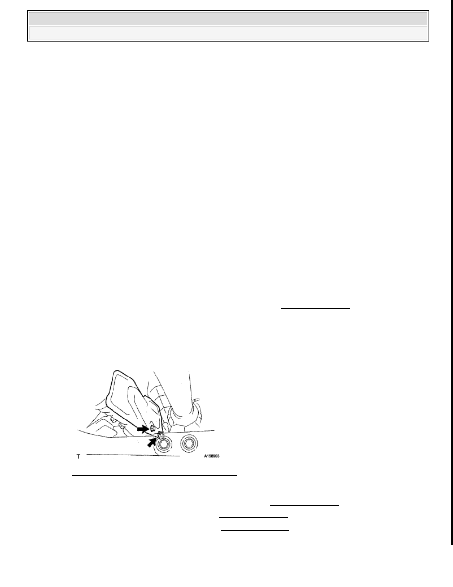
Install the heat insulator with the 2 bolts  

Torque: 16 N*m (163 kgf*cm, 12 ft.*lbf)  

Fig. 22: Locating Heat Insulator With Bolts 
Courtesy of TOYOTA MOTOR SALES, U.S.A., INC. 

11

CONNECT COOLER COMPRESSOR ASSEMBLY (See INSTALLATION )  

12

INSTALL GENERATOR ASSEMBLY (See INSTALLATION )  

13

CONNECT VANE PUMP ASSEMBLY (See INSTALLATION )  


2009 Toyota Tundra 

2009 ENG NE Exhaust (3UR-FBE) - Tundra


14

INSTALL ENGINE OIL LEVEL DIPSTICK GUIDE (See INSTALLATION )  

15

INSTALL FAN SHROUD (See INSTALLATION )  

16

INSTALL FAN AND GENERATOR V BELT (See INSTALLATION )  

17

CONNECT OUTLET RADIATOR HOSE  

18

CONNECT INLET RADIATOR HOSE  

19

INSTALL AIR CLEANER ASSEMBLY (See INSTALLATION )  

20

INSTALL AIR CLEANER HOSE ASSEMBLY (See INSTALLATION )  

21

CONNECT CABLE TO NEGATIVE BATTERY TERMINAL 

22

ADD ENGINE COOLANT (See COOLANT )  

23

INSPECT FOR COOLANT LEAK (See COOLING SYSTEM )  

24

INSPECT FOR EXHAUST GAS LEAK 

If gas is leaking, tighten the areas necessary to stop the leak  Replace damaged parts as necessary  

25

INSTALL FRONT FENDER APRON SEAL REAR LH 

a

Install the fender apron seal with the 5 clips   

26

INSTALL FRONT FENDER APRON SEAL LH 

a

Install the fender apron seal with the 6 clips   

27

INSTALL FRONT FENDER APRON SEAL REAR RH 

a

Install the fender apron seal with the 5 clips   

28

INSTALL FRONT FENDER APRON SEAL RH 

a

Install the fender apron seal with the 6 clips   

29

INSTALL NO. 1 ENGINE UNDER COVER (See REPLACEMENT )  

30

INSTALL V-BANK COVER SUB-ASSEMBLY (See INSTALLATION )  

EXHAUST PIPE (FOR REGULAR CAB STANDARD DECK) 

COMPONENTS 

NOTE:

When disconnecting the cable some systems need to be initialized after 
the cable is reconnected (See INITIALIZATION ).


2009 Toyota Tundra 

2009 ENG NE Exhaust (3UR-FBE) - Tundra


Fig. 23: Identifying Exhaust Pipe Components With Torque Specifications (1 Of 3) 
Courtesy of TOYOTA MOTOR SALES, U.S.A., INC. 


2009 Toyota Tundra 

2009 ENG NE Exhaust (3UR-FBE) - Tundra


Fig. 24: Identifying Exhaust Pipe Components With Torque Specifications (2 Of 3) 
Courtesy of TOYOTA MOTOR SALES, U.S.A., INC. 


2009 Toyota Tundra 

2009 ENG NE Exhaust (3UR-FBE) - Tundra


Content   ..  2065  2066  2067  2068   ..