Toyota Tundra. Manual - part 199
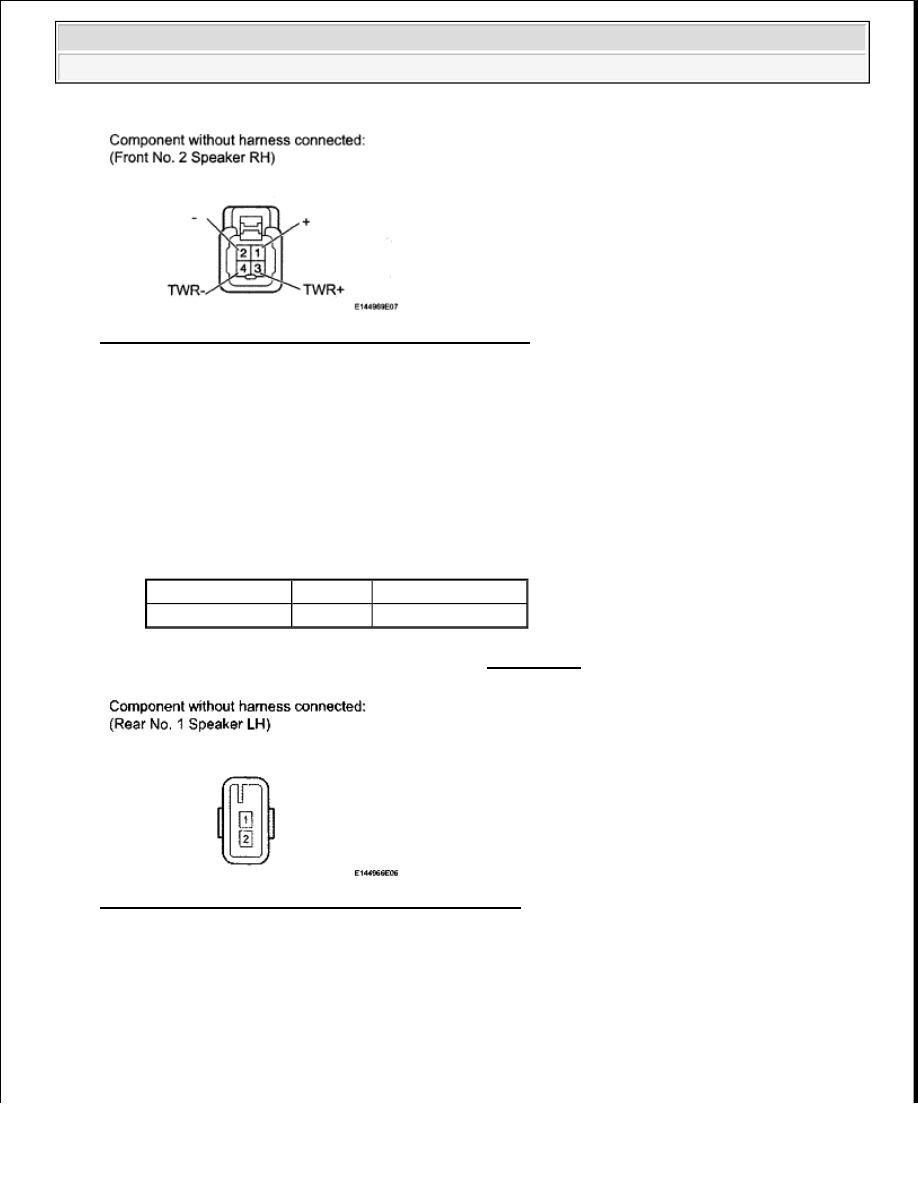
Fig. 174: Identifying K10 Speaker Connector Terminals
Courtesy of TOYOTA MOTOR SALES, U.S.A., INC.
OK: Go to Next Step
12. INSPECT REAR NO. 1 SPEAKER LH
a. Disconnect the O7 speaker connector.
b. Measure the resistance according to the value(s) in the table below.
Standard resistance
TESTER CONNECTION SPECIFIED CONDITION
NG: REPLACE REAR NO. 1 SPEAKER LH (see REMOVAL )
Fig. 175: Identifying O7 Speaker Connector Terminals
Courtesy of TOYOTA MOTOR SALES, U.S.A., INC.
OK: Go to Next Step
13. INSPECT REAR NO. 1 SPEAKER RH
a. Disconnect the O1 speaker connector.
b. Measure the resistance according to the value(s) in the table below.
Tester Connection Condition Specified Condition
1 - 2
Always
1.5 to 2.1 ohms
2009 Toyota Tundra
2009 ACCESSORIES AND EQUIPMENT Audio/Visual - Tundra