Toyota Tundra. Manual - part 1871


  Index      Toyota     Toyota Tundra (2007-2010 year) - Service and Repair Manual


Search            copyright infringement  


Content   ..  1869  1870  1871  1872   ..


Toyota Tundra. Manual - part 1871


Courtesy of TOYOTA MOTOR SALES, U.S.A., INC. 

DISASSEMBLY 

1

REMOVE INTAKE VALVE 

a

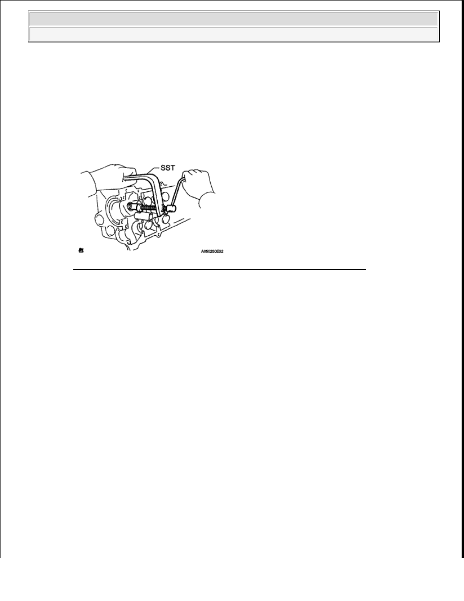
Using SST, compress the compression spring and remove the 2 valve spring retainer locks  

SST 09202-70020 (09202-00010, 09202-01010, 09202-01020)  

Fig. 174: Compressing Spring And Valve Spring Retainer Locks Using SST 
Courtesy of TOYOTA MOTOR SALES, U.S.A., INC. 

b

Remove the spring retainer, compression spring, valve and spring seat  

HINT: 

Arrange the removed parts in the correct order  

2

REMOVE EXHAUST VALVE 

a

Using SST, compress the compression spring and remove the 2 valve spring retainer locks  

SST 09202-70020 (09202-00010, 09202-01010, 09202-01020)  

b

Remove the spring retainer, compression spring, valve and spring seat  

HINT: 

Arrange the removed parts in the correct order  


2009 Toyota Tundra 

2009 ENGINE Engine Mechanical (2UZ-FE) - Tundra


Fig. 175: Compressing Compression Spring And Valve Spring Retainer Locks Using SST 
Courtesy of TOYOTA MOTOR SALES, U.S.A., INC. 

3

REMOVE VALVE STEM OIL SEAL 

a

Using needle nose pliers, remove the oil seals  

Fig. 176: Using Needle Nose Pliers To Remove Oil Seals 
Courtesy of TOYOTA MOTOR SALES, U.S.A., INC. 

INSPECTION 

1

CLEAN CYLINDER HEAD SUB-ASSEMBLY 

a

Using a gasket scraper, remove all the gasket material from the cylinder block contact surface  

Fig. 177: Using Gasket Scraper To Remove Gasket Material From Cylinder Block Contact 
Surface
 

NOTE:

Be careful not to scratch the cylinder block contact surface.


2009 Toyota Tundra 

2009 ENGINE Engine Mechanical (2UZ-FE) - Tundra


Courtesy of TOYOTA MOTOR SALES, U.S.A., INC. 

b

Using a wire brush, remove all the carbon from the combustion chambers  

Fig. 178: Using Wire Brush To Remove Carbon Of Combustion Chambers 
Courtesy of TOYOTA MOTOR SALES, U.S.A., INC. 

c

Using a valve guide bushing brush and solvent, clean all the guide bushes  

Fig. 179: Identifying Valve Guide Bushing Brush 
Courtesy of TOYOTA MOTOR SALES, U.S.A., INC. 

d

Using a soft brush and solvent, thoroughly clean the cylinder head  

Fig. 180: Using Brush & Solvent To Clean Cylinder Head 
Courtesy of TOYOTA MOTOR SALES, U.S.A., INC. 

NOTE:

Be careful not to scratch the cylinder block contact surface.


2009 Toyota Tundra 

2009 ENGINE Engine Mechanical (2UZ-FE) - Tundra


2

INSPECT CYLINDER HEAD SUB-ASSEMBLY 

a

Using a precision straightedge and feeler gauge, measure the surfaces contacting the cylinder block 
and manifolds for warpage  

Maximum warpage  

ITEM SPECIFICATION 

If the warpage is greater than the maximum, replace the cylinder head  

Fig. 181: Measuring Surfaces Contacting Cylinder Block & Manifolds For Warpage Using 
Straight Edge & Feeler Gauge
 
Courtesy of TOYOTA MOTOR SALES, U.S.A., INC. 

b

Using a dye penetrant, check the combustion chamber, intake ports, exhaust ports and cylinder 
block surface for cracks  If the cylinder head is cracked, replace it  

Item

Specified Condition

Cylinder block side 0 10 mm (0 00394 in )

Intake manifold side 0 10 mm (0 00394 in )

Exhaust manifold side 0 10 mm (0 00394 in )


2009 Toyota Tundra 

2009 ENGINE Engine Mechanical (2UZ-FE) - Tundra


Content   ..  1869  1870  1871  1872   ..