Toyota Tundra. Manual - part 1853


  Index      Toyota     Toyota Tundra (2007-2010 year) - Service and Repair Manual


Search            copyright infringement  


Content   ..  1851  1852  1853  1854   ..


Toyota Tundra. Manual - part 1853
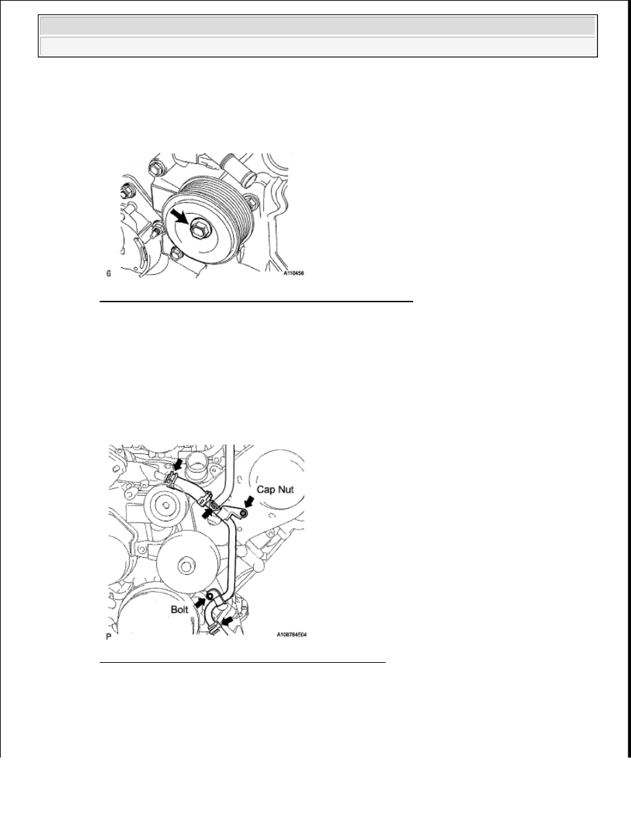


a

Install the idler pulley and cover plate with the bolt  

Torque: 39 N*m (398 kgf*cm, 29 ft.*lbf)  

Fig. 70: Identifying Idler Pulley And Cover Plate With Bolt 
Courtesy of TOYOTA MOTOR SALES, U.S.A., INC. 

14

INSTALL OIL COOLER PIPE 

a

Using needle-nose pliers, grip the claws of the clamps and slide the clamps to connect the 3 water 
by-pass hoses   

b

Install the oil cooler pipe with the cap nut and bolt  

Torque: 7.5 N*m (76 kgf*cm, 66 in.*lbf)  

Fig. 71: Identifying Oil Cooler Pipe Cap Nut And Bolt 
Courtesy of TOYOTA MOTOR SALES, U.S.A., INC. 

15

CONNECT COOLER COMPRESSOR ASSEMBLY 

a

Connect the compressor  Then install it and the No  1 compressor stay with the nut and 3 bolts  

Torque: for bolt  


2009 Toyota Tundra 

2009 ENGINE Engine Mechanical (2UZ-FE) - Tundra


47 N*m (479 kgf*cm, 35 ft.*lbf)  

for nut  

25 N*m (255 kgf*cm, 18 ft.*lbf)  

b

Connect the connector  

Fig. 72: Locating Cooler Compressor Assembly Bolts And Nut 
Courtesy of TOYOTA MOTOR SALES, U.S.A., INC. 

16

INSTALL GENERATOR ASSEMBLY (See INSTALLATION )  

17

CONNECT VANE PUMP ASSEMBLY 

a

Connect the vane pump with the nut and 2 bolts  

Torque: 28 N*m (286 kgf*cm, 21 ft.*lbf)  

b

Connect the connector   

18

INSTALL FLUID COUPLING ASSEMBLY 

a

Set the fan pulley to the fan bracket   

b

Set the fan together with the fan shroud into the vehicle  

c

Temporarily install the fan to the fan pulley with the 4 fluid coupling nuts   

d

Install the fan shroud with the 2 bolts  

Torque: 6.5 N*m (66 kgf*cm, 58 in.*lbf)  

NOTE:

Be careful not to damage the radiator core.  

Make sure to attach the 2 claws of the fan shroud to the vehicle. 


2009 Toyota Tundra 

2009 ENGINE Engine Mechanical (2UZ-FE) - Tundra


Fig. 73: Identifying Fan Coupling Bolts 
Courtesy of TOYOTA MOTOR SALES, U.S.A., INC. 

e

Tighten the 4 fluid coupling nuts  

Torque: 29 N*m (296 kgf*cm, 21 ft.*lbf)  

Fig. 74: Locating Fluid Coupling Nuts 
Courtesy of TOYOTA MOTOR SALES, U.S.A., INC. 

19

INSTALL FAN AND GENERATOR V BELT (See INSTALLATION )  

20

INSTALL RADIATOR HOSE OUTLET  

21

INSTALL RADIATOR HOSE INLET  

22

INSTALL AIR CLEANER ASSEMBLY (See INSTALLATION )  

23

INSTALL AIR CLEANER HOSE ASSEMBLY (See INSTALLATION )  

24

INSTALL THROTTLE BODY COVER SUB-ASSEMBLY (See INSTALLATION )  

25

ADD ENGINE COOLANT (See REPLACEMENT )  

26

CONNECT CABLE TO NEGATIVE BATTERY TERMINAL 

27

INSPECT FOR COOLANT LEAK (See ON-VEHICLE INSPECTION )  

28

INSPECT IGNITION TIMING (See ON-VEHICLE INSPECTION )  

29

INSPECT ENGINE IDLE SPEED (See ON-VEHICLE INSPECTION )  

30

INSTALL NO. 1 ENGINE UNDER COVER (See REPLACEMENT )  

NOTE:

Some systems need to be initialized after the cable is reconnected (see 
INITIALIZATION ).


2009 Toyota Tundra 

2009 ENGINE Engine Mechanical (2UZ-FE) - Tundra


CAMSHAFT (FOR BANK 1) 

COMPONENTS 

Fig. 75: Identifying Bank 1 Camshaft Replacement Components With Torque Specifications (1 Of 2) 
Courtesy of TOYOTA MOTOR SALES, U.S.A., INC. 


2009 Toyota Tundra 

2009 ENGINE Engine Mechanical (2UZ-FE) - Tundra


Content   ..  1851  1852  1853  1854   ..