Toyota Tundra. Manual - part 1805


  Index      Toyota     Toyota Tundra (2007-2010 year) - Service and Repair Manual


Search            copyright infringement  


Content   ..  1803  1804  1805  1806   ..


Toyota Tundra. Manual - part 1805
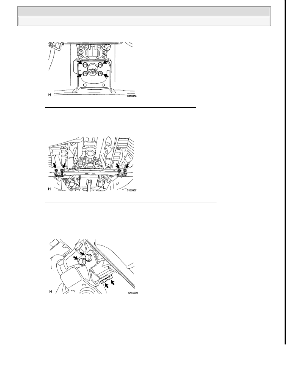


Fig. 194: Locating Rear No. 1 Engine Mounting Insulator Bolts 
Courtesy of TOYOTA MOTOR SALES, U.S.A., INC. 

b

Remove the 4 nuts, 4 washers, 4 bolts and No  3 frame crossmember  

Fig. 195: Locating No. 3 Frame Crossmember Nuts, Washers And Bolts 
Courtesy of TOYOTA MOTOR SALES, U.S.A., INC. 

50

REMOVE REAR NO. 1 ENGINE MOUNTING INSULATOR 

a

Remove the 4 bolts and engine mounting insulator  

Fig. 196: Locating Rear No. 1 Engine Mounting Insulator Bolts 
Courtesy of TOYOTA MOTOR SALES, U.S.A., INC. 

51

DISCONNECT WIRE HARNESS AND CONNECTOR (See REMOVAL )  

52

DISCONNECT NO. 1 WATER BY-PASS PIPE (See REMOVAL )  

53

REMOVE AUTOMATIC TRANSMISSION ASSEMBLY (See REMOVAL )  


2009 Toyota Tundra 

2009 ENGINE Engine Mechanical (1GR-FE) - Tundra


54

REMOVE ENGINE ASSEMBLY 

a

Install the 2 engine hangers with the 4 bolts shown below  

Part No.:  

ITEM REFERENCE 

Torque: 33 N*m (336 kgf*cm, 24 ft.*lbf)  

Fig. 197: Locating Engine Hangers & Bolts 
Courtesy of TOYOTA MOTOR SALES, U.S.A., INC. 

b

Attach the engine sling device and hang the engine with the chain block  

Fig. 198: Hanging Engine With Chain Block Using Engine Sling Device 
Courtesy of TOYOTA MOTOR SALES, U.S.A., INC. 

c

Remove the 2 nuts and 4 bolts from the front engine mounting insulator LH and RH   

d

Lift the engine out of the vehicle carefully  

Item

Part No.

No  1 engine hanger 12281-31060
No  2 engine hanger 12282-31040

Bolt

90119-08A87

NOTE:

Make sure the engine is clear of all wiring and hoses.


2009 Toyota Tundra 

2009 ENGINE Engine Mechanical (1GR-FE) - Tundra


e

Remove the front engine mounting insulator LH and RH   

f

Place the engine onto a working bench  

Fig. 199: Locating Front Engine Mounting Insulator Nuts & Bolts 
Courtesy of TOYOTA MOTOR SALES, U.S.A., INC. 

55

REMOVE DRIVE PLATE AND RING GEAR 

a

Using SST, hold the crankshaft  

SST 09213-54015 (91651-60855), 09330-00021  

Fig. 200: Holding Crankshaft Using SST 
Courtesy of TOYOTA MOTOR SALES, U.S.A., INC. 

b

Remove the 8 bolts, rear spacer, drive plate and front spacer  


2009 Toyota Tundra 

2009 ENGINE Engine Mechanical (1GR-FE) - Tundra


Fig. 201: Locating Drive Plate And Ring Gear Bolts 
Courtesy of TOYOTA MOTOR SALES, U.S.A., INC. 

56

INSTALL ENGINE STAND 

a

Install the engine onto an engine stand with the bolts   

57

REMOVE ENGINE HANGER 

a

Remove the 4 bolts and 2 engine hangers  

Fig. 202: Locating Engine Hangers & Bolts 
Courtesy of TOYOTA MOTOR SALES, U.S.A., INC. 

INSTALLATION 

1

INSTALL ENGINE HANGER 

a

Install the 2 engine hangers with the 4 bolts shown below  

Fig. 203: Locating Engine Hangers & Bolts 


2009 Toyota Tundra 

2009 ENGINE Engine Mechanical (1GR-FE) - Tundra


Content   ..  1803  1804  1805  1806   ..