Toyota Tundra. Manual - part 1758


  Index      Toyota     Toyota Tundra (2007-2010 year) - Service and Repair Manual


Search            copyright infringement  


Content   ..  1756  1757  1758  1759   ..


Toyota Tundra. Manual - part 1758


Torque: for bolt  

18 N*m (184 kgf*cm, 13 ft.*lbf) for nut  

12 N*m (122 kgf*cm, 9 ft.*lbf)  

b

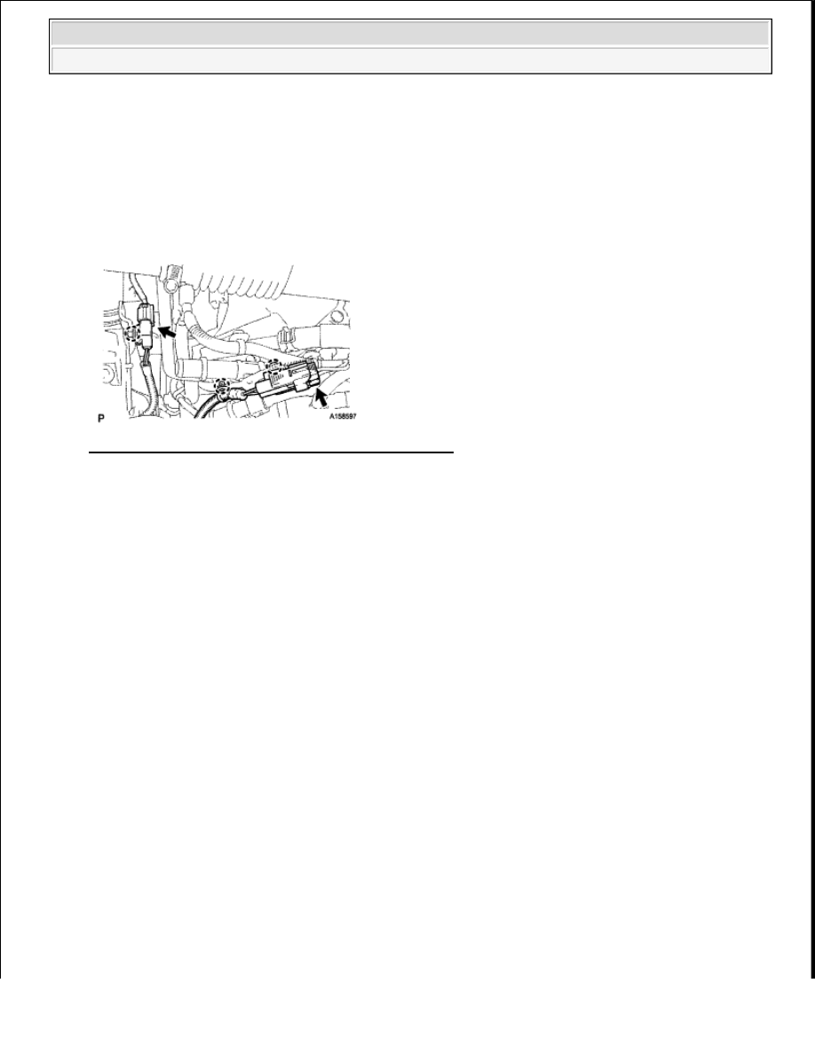
Connect the 2 air pump connectors and attach the 3 wire harness claws   

Fig. 30: Identifying Air Pump Connectors And Claws 
Courtesy of TOYOTA MOTOR SALES, U.S.A., INC. 

5

INSTALL NO. 3 AIR INJECTION SYSTEM HOSE 

a

Connect the No  3 hose so that its paint mark aligns with the air pump's rib as shown in the 
illustration below labeled A   

b

Connect the clamp to the No  3 hose shown in the illustration below labeled B  Then insert the 
clamp's clip into the body hole  

HINT: 

Align the paint mark of the No  3 hose with the edge of the clamp  

c

Connect the No  3 hose to the air tube shown in the illustration below labeled C  

HINT: 

Make sure the paint mark of the No  3 hose is facing upward   

Make sure the direction of the hose clamp is as shown in the illustration   

d

Connect the clamp to the No  3 hose and wire harness shown in the illustration below labeled D  
Then insert the clamp's clip into the body hole  

HINT: 

Align the pain mark of the No  3 hose and paint mark of the wire harness with the edge of the 
clamp  

6

INSTALL NO. 2 AIR INJECTION SYSTEM HOSE 


2009 Toyota Tundra 

2009 ENG NE Emission Control (3UR-FE) - Tundra


a

Connect the No  2 hose so that its paint mark aligns with the air pump's rib as shown in the 
illustration below labeled E   

b

Connect the No  2 hose to the air tube shown in the illustration below labeled F  

HINT: 

Make sure the paint mark of the No  2 hose is facing upward   

Make sure the direction of the hose clamp is as shown in the illustration   

c

Connect the white colored clamp to the No  2 hose and wire harness shown in the illustration below 
labeled G  

HINT: 

Make sure the paint mark of the No  2 hose is facing upward   

Make sure the direction of the hose clamp is as shown in the illustration   

d

Connect the black colored clamp to the No  2 hose and wire harness shown in the illustration below 
labeled H  Then insert the clamp's clip into the body hole  


2009 Toyota Tundra 

2009 ENG NE Emission Control (3UR-FE) - Tundra


Fig. 31: Connecting Black Colored Clamp To No. 2 Hose 
Courtesy of TOYOTA MOTOR SALES, U.S.A., INC. 

7

CONNECT FRONT FENDER APRON SEAL RH 

a

Connect the fender apron seal with the 2 clips  

Fig. 32: Identifying Fender Apron Seal With Clips 


2009 Toyota Tundra 

2009 ENG NE Emission Control (3UR-FE) - Tundra


Courtesy of TOYOTA MOTOR SALES, U.S.A., INC. 

8

INSTALL FRONT FENDER LINER RH 

a

Install the fender liner with the 9 clips  

Fig. 33: Identifying Fender Liner Clips 
Courtesy of TOYOTA MOTOR SALES, U.S.A., INC. 

AIR SWITCHING VALVE 

COMPONENTS 


2009 Toyota Tundra 

2009 ENG NE Emission Control (3UR-FE) - Tundra


Content   ..  1756  1757  1758  1759   ..