Toyota Tundra. Manual - part 1746


  Index      Toyota     Toyota Tundra (2007-2010 year) - Service and Repair Manual


Search            copyright infringement  


Content   ..  1744  1745  1746  1747   ..


Toyota Tundra. Manual - part 1746
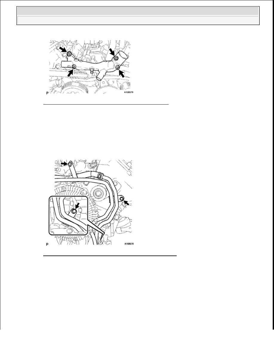


Fig. 57: Locating Front Water By-Pass Joint And Nuts 
Courtesy of TOYOTA MOTOR SALES, U.S.A., INC. 

b

Connect the engine coolant temperature sensor connector   

6

CONNECT NO. 2 WATER BY-PASS PIPE SUB-ASSEMBLY (w/ Trailer Towing System) 

a

Connect the No  2 water by-pass pipe with the 3 bolts  

Torque: 10 N*m (102 kgf*cm, 7 ft.*lbf)  

Fig. 58: Locating No. 2 Water By-Pass Pipe Sub-Assembly 
Courtesy of TOYOTA MOTOR SALES, U.S.A., INC. 

7

CONNECT NO. 2 WATER BY-PASS HOSE 

a

Connect the No  2 water by-pass hose to the water by-pass joint  


2009 Toyota Tundra 

2009 ENG NE Emission Control (3UR-FBE) - Tundra


Fig. 59: Locating No. 2 Water By-Pass Hose 
Courtesy of TOYOTA MOTOR SALES, U.S.A., INC. 

8

CONNECT NO. 1 WATER BY-PASS HOSE 

a

Connect the No  1 water by-pass hose to the water by-pass joint and water inlet housing   

9

INSTALL NO. 1 ENGINE COVER 

HINT: 

Align the No  1 engine cover cutouts with the air tube   

Align the No  1 engine cover with the air switching valve surface and cylinder head wall  

Fig. 60: Installing No. 1 Engine Cover 
Courtesy of TOYOTA MOTOR SALES, U.S.A., INC. 

NOTE:

Make sure that the No. 1 engine cover is level with the top surface of the 
intake port of the cylinder head for 1 and 2.


2009 Toyota Tundra 

2009 ENG NE Emission Control (3UR-FBE) - Tundra


10

CONNECT FUEL TUBE CLAMP 

a

Connect the fuel tube clamp to the bracket  

Fig. 61: Locating Fuel Tube Clamp To Bracket 
Courtesy of TOYOTA MOTOR SALES, U.S.A., INC. 

11

INSTALL NO. 2 ENGINE COVER 

HINT: 

Align the No  2 engine cover cutout with the air tube   

Align the No  2 engine cover with the front water bypass joint and cylinder head wall  

NOTE:

Make sure that the No. 2 engine cover is level with the top surface of the 
intake port if the cylinder head.


2009 Toyota Tundra 

2009 ENG NE Emission Control (3UR-FBE) - Tundra


Fig. 62: Identifying No. 2 Engine Cover 
Courtesy of TOYOTA MOTOR SALES, U.S.A., INC. 

12

INSTALL FAN SHROUD 

a

Install the fan shroud (See INSTALLATION )   

13

INSTALL INTAKE MANIFOLD 

a

Install the intake manifold (See INSTALLATION )   

14

INSTALL EXHAUST MANIFOLD SUB-ASSEMBLY 

a

Install the exhaust manifold (See INSTALLATION )   

AIR INJECTION DRIVER 

COMPONENTS 


2009 Toyota Tundra 

2009 ENG NE Emission Control (3UR-FBE) - Tundra


Content   ..  1744  1745  1746  1747   ..