Toyota Tundra. Manual - part 1722


  Index      Toyota     Toyota Tundra (2007-2010 year) - Service and Repair Manual


Search            copyright infringement  


Content   ..  1720  1721  1722  1723   ..


Toyota Tundra. Manual - part 1722


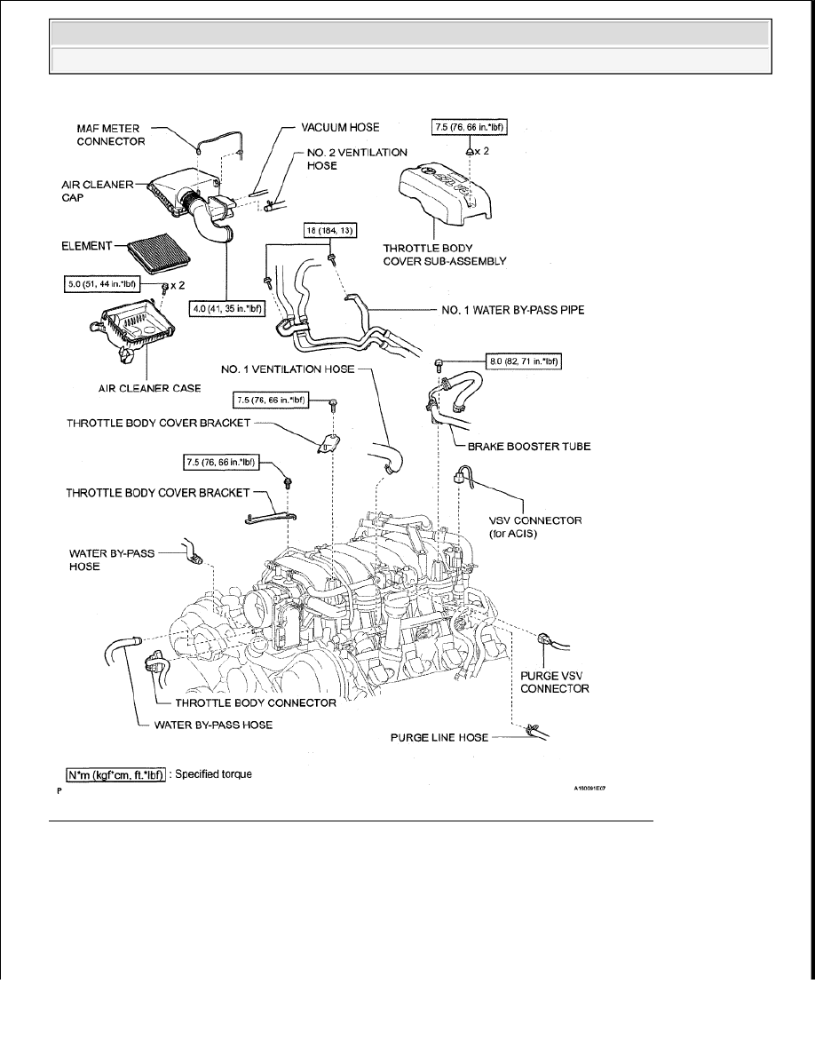
Fig. 15: Identifying Air Pump Components (Bank 1) With Torque Specifications (2 Of 3) 
Courtesy of TOYOTA MOTOR SALES, U.S.A., INC. 


2009 Toyota Tundra 

2009 ENG NE Emission Control (2UZ-FE) - Tundra


Fig. 16: Identifying Air Pump Components (Bank 1) With Torque Specifications (3 Of 3) 
Courtesy of TOYOTA MOTOR SALES, U.S.A., INC. 

REMOVAL 


2009 Toyota Tundra 

2009 ENG NE Emission Control (2UZ-FE) - Tundra


1

DISCONNECT CABLE FROM NEGATIVE BATTERY TERMINAL 

2

REMOVE INTAKE MANIFOLD ASSEMBLY 

a

Remove the intake manifold (See REMOVAL )   

3

REMOVE WATER BYPASS PIPE SUB-ASSEMBLY 

a

Disconnect the connector clamp   

b

Remove the bolt   

c

Pull out the water bypass pipe  

Fig. 17: Identifying Water By-Pass Pipe 
Courtesy of TOYOTA MOTOR SALES, U.S.A., INC. 

d

REMOVE NO. 4 AIR INJECTION SYSTEM HOSE 

Fig. 18: Identifying No. 4 Air Injection System Hose 
Courtesy of TOYOTA MOTOR SALES, U.S.A., INC. 

NOTE:

Some systems need to be initialized after the cable is reconnected 
(see INITIALIZATION ).  

After the ignition switch is turned OFF, the navigation system 
requires approximately 90 seconds to record various types of 
memory and settings. As a result, after turning the ignition switch 
OFF, wait 90 seconds or more before disconnecting the cable from 
the negative (-) battery terminal.  


2009 Toyota Tundra 

2009 ENG NE Emission Control (2UZ-FE) - Tundra


e

Remove the O-ring from the water bypass pipe   

4

REMOVE AIR PUMP ASSEMBLY 

a

Disconnect the air pump connector   

b

Remove the 2 bolts, 2 nuts and air pump   

DISASSEMBLY 

1

REMOVE AIR PUMP 

a

Remove the 3 bolts, 3 collars, 3 insulators and air pump  

Fig. 19: Identifying Air Pump And Fasteners 
Courtesy of TOYOTA MOTOR SALES, U.S.A., INC. 

INSPECTION 

1

INSPECT AIR PUMP 

a

Measure the resistance according to the value(s) in the table below  

Standard resistance  

AIR PUMP STANDARD RESISTANCE SPECIFICATION 

Tester Connection Condition Specified Condition

1 - 2

20°C (68°F)

0 4 to 1 0 ohms

1 - Body ground

Always

10 kohms or higher

2 - Body ground


2009 Toyota Tundra 

2009 ENG NE Emission Control (2UZ-FE) - Tundra


Content   ..  1720  1721  1722  1723   ..