Toyota Tundra. Manual - part 168


  Index      Toyota     Toyota Tundra (2007-2010 year) - Service and Repair Manual


Search            copyright infringement  


Content   ..  166  167  168  169   ..


Toyota Tundra. Manual - part 168


B: REPLACE FRONT NO. 2 SPEAKER (see REMOVAL ) 

C: REPLACE FRONT NO. 2 SPEAKER (see REMOVAL ) 

A: REPAIR OR REPLACE HARNESS OR CONNECTOR  

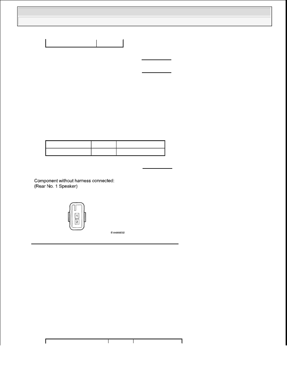
7. INSPECT REAR NO. 1 SPEAKER 

a. Disconnect the O1 and O7 speaker connectors.  

b. Measure the resistance according to the value(s) in the table below. 

Standard resistance  

TESTER CONNECTION SPECIFIED CONDITION 

NG: REPLACE REAR NO. 1 SPEAKER (see REMOVAL ) 

Fig. 91: Identifying Rear No. 1 Speaker Connector Terminals 
Courtesy of TOYOTA MOTOR SALES, U.S.A., INC. 

OK: Go to Next Step  

8. CHECK HARNESS AND CONNECTOR (RADIO RECEIVER - REAR NO. 1 SPEAKER) 

a. Disconnect the K2 receiver connector.  

b. Disconnect the O1 and O7 speaker connectors.  

c. Measure the resistance according to the value(s) in the table below. 

Standard resistance:  

for LH  

TESTER CONNECTION SPECIFIED CONDITION 

OK (for Double Cab)

C

Tester Connection Condition Specified Condition

1 - 2

Always

3.2 to 4.8 ohms


2009 Toyota Tundra 

2009 ACCESSORIES AND EQUIPMENT Audio/Visual - Tundra


for RH  

TESTER CONNECTION SPECIFIED CONDITION 

Fig. 92: Checking Harness And Connector (Radio Receiver - Rear No. 1 Speaker) 
Courtesy of TOYOTA MOTOR SALES, U.S.A., INC. 

Result:  

RESULT REFERENCE 

Tester Connection

Condition Specified Condition

K2-2 (RL+) - O7-1

Always

Below 1 ohms

K2-6 (RL-) - O7-2

K2-2 (RL+) - Body ground

Always

10 kohms or higher

K2-6 (RL-) - Body ground

Tester Connection

Condition Specified Condition

K2-1 (RR+J- O1-1

Always

Below 1 ohms

K2-3(RR-) - O1-2

K2-1 (RR+) - Body ground

Always

10 kohms or higher

K2-3 (RR-) - Body ground

Result

Proceed to

NG

A

OK (for Column Shift Type)

B


2009 Toyota Tundra 

2009 ACCESSORIES AND EQUIPMENT Audio/Visual - Tundra


B: REPLACE RADIO RECEIVER (see REMOVAL ) 

C: REPLACE RADIO RECEIVER (see REMOVAL ) 

A: REPAIR OR REPLACE HARNESS OR CONNECTOR  

SOUND SIGNAL CIRCUIT BETWEEN RADIO RECEIVER AND STEREO COMPONENT 
AMPLIFIER 

DESCRIPTION 

The radio receiver sends a sound signal to the stereo component amplifier through this circuit. 

The sound signal that has been sent is amplified by the stereo component amplifier, and then is sent to the 
speakers. 

If there is an open or short in the circuit, sound cannot be heard from the speakers even if there is no 
malfunction in the stereo component amplifier or speakers. 

WIRING DIAGRAM 

Fig. 93: Sound Signal Circuit between Radio Receiver and Stereo Component Amplifier - Wiring 
Diagram
 
Courtesy of TOYOTA MOTOR SALES, U.S.A., INC. 

INSPECTION PROCEDURE 

1. CHECK HARNESS AND CONNECTOR (RADIO RECEIVER - STEREO COMPONENT 

AMPLIFIER) 

a. Disconnect the K4 receiver connector.  

OK (for Floor Shift Type)

C


2009 Toyota Tundra 

2009 ACCESSORIES AND EQUIPMENT Audio/Visual - Tundra


b. Disconnect the K15 amplifier connector.  

c. Measure the resistance according to the value(s) in the table below. 

Standard resistance  

TESTER CONNECTION SPECIFIED CONDITION 

NG: REPAIR OR REPLACE HARNESS OR CONNECTOR  

Fig. 94: Identifying K4 And K15 Connectors Terminals 
Courtesy of TOYOTA MOTOR SALES, U.S.A., INC. 

Tester Connection

Condition Specified Condition

K4-9(L+) - K15-3(L+)

Always

Below 1 ohms

K4-19(L-) - K15-2(L-)

K4-8(R+) - K15-5(R+)
K4-18(R-) - K15-4(R-)

K4-10(SLD) - K15-6 (SLD)

K4-9 (L+) - Body ground

Always

10 kohms or higher

K4-19 (L-) - Body ground

K4-8 (R+) - Body ground

K4-18 (R-) - Body ground


2009 Toyota Tundra 

2009 ACCESSORIES AND EQUIPMENT Audio/Visual - Tundra


Content   ..  166  167  168  169   ..