Toyota Tundra. Manual - part 1645


  Index      Toyota     Toyota Tundra (2007-2010 year) - Service and Repair Manual


Search            copyright infringement  


Content   ..  1643  1644  1645  1646   ..


Toyota Tundra. Manual - part 1645


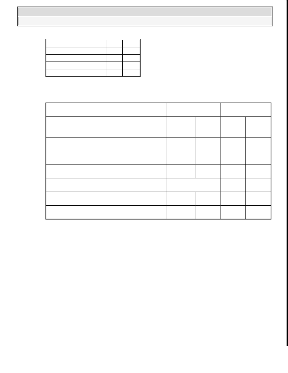
When malfunctioning: 

ACTIVE TEST REFERENCE VALUE (MALFUNCTIONING 

B: REPLACE FUEL SUCTION WITH PUMP AND GAUGE TUBE ASSEMBLY (See 
REMOVAL ) 

A: Go to Next Step  

5. CHECK FUEL PRESSURE SWITCHING VALVE (POWER SOURCE) 

a. Disconnect the fuel pressure switching valve connector. 

Long FT #2

-2.4% -2.4%

AF Lambda B1 S1

0.99

0.96

AF Lambda B2 S1

1.00

0.96

Alcohol Density Estimate 73%

73%

Alcohol Density Learning Compl Compl

Change in Short FT while performing Active 
Test

Less than 7%

7% or more

Active Test State

Low

High

Low

High

Fuel pressure when there is fuel leak from fuel pipes

Below 270 
kPa

Below 
370 kPa

Below 
270 kPa

Below 
370 kPa

Fuel pressure when fuel pressure in high pressure 
side pressure regulator cannot remain stable

Below 270 
kPa

Below 
370 kPa

Below 
270 kPa

Below 
370 kPa

Fuel pressure when fuel pump ECU is 
malfunctioning and drive voltage stuck at low

270 to 330 
kPa

Below 
370 kPa

-

-

Fuel pressure when fuel pump ECU is 
malfunctioning and drive voltage stuck at high

370 kPa or 
higher

370 to 430 
kPa

-

-

Fuel pressure when fuel pressure switching valve 
stuck

No change in pressure -

-

Fuel pressure when fuel pressure in low pressure 
side pressure regulator cannot remain stable

-

-

Below 
270 kPa

370 to 430 
kPa

Fuel pressure when fuel pump discharge ability 
decreases

-

Below 
370 kPa

-

Below 
370 kPa


2009 Toyota Tundra 

2009 ENGINE PERFORMANCE Engine Control System (3UR-FBE) - Tundra


Saturday, June 19, 2010 7:34:49 PM

Page 673 

© 2006 Mitchell Repair Information Company, LLC. 

Fig. 321: Identifying Fuel Pressure Switching Valve Connector Terminals 
Courtesy of TOYOTA MOTOR SALES, U.S.A., INC. 

b. Connect the Techstream to the DLC3.  

c. Enter the following menus: Powertrain/Engine and ECT/Active Test/Activate the Fuel Pressure 

Switching Valve.  

d. Operate the fuel pressure switching valve.  

e. Measure the voltage according to the value (s) in the table below. 

Standard Voltage  

VOLTAGE SPECIFIED CONDITION 

NG: Go to step 7 

OK: Go to Next Step  

6. INSPECT FUEL PRESSURE SWITCHING VALVE 

a. Inspect the fuel pressure switching valve (See INSPECTION ). 

NG: REPLACE FUEL PRESSURE SWITCHING VALVE (See REMOVAL ) 

OK: REPLACE FUEL SUCTION WITH PUMP AND GAUGE TUBE ASSEMBLY (See 
REMOVAL ) 

7. INSPECT RELAY (F/PMP VSV) 

a. Inspect the F/PMP VSV relay (See ON-VEHICLE INSPECTION ). 

Tester Connection

Condition

Specified Condition

1 - 2

High selected in Active Test

11 to 14 V


2009 Toyota Tundra 

2009 ENGINE PERFORMANCE Engine Control System (3UR-FBE) - Tundra


Saturday, June 19, 2010 7:34:49 PM

Page 674 

© 2006 Mitchell Repair Information Company, LLC. 

NG: REPLACE RELAY (F/PMP VSV) (See ON-VEHICLE INSPECTION ) 

OK: Go to Next Step  

8. CHECK RELAY (F/PMP VSV POWER SOURCE) 

a. Remove the fuel pressure control valve relay (F/PMP VSV) from the engine room relay block. 

Fig. 322: Identifying Fuel Pressure Control Valve Relay Connector Terminals 
Courtesy of TOYOTA MOTOR SALES, U.S.A., INC. 

b. Measure the voltage according to the value (s) in the table below. 

Standard Voltage  

VOLTAGE SPECIFIED CONDITION 

NG: GO TO ECM POWER SOURCE CIRCUIT  

OK: Go to Next Step  

9. CHECK HARNESS AND CONNECTOR (FUEL PRESSURE SWITCHING VALVE - F/PMP 

RELAY, BODY GROUND) 

a. Disconnect the fuel pressure switching valve connector.  

b. Remove the fuel pressure control valve relay (F/PMP VSV) from the engine room relay block. 

Tester Connection

Condition Specified Condition

F/PMP VSV relay (5) - Body ground Always

11 to 14 V


2009 Toyota Tundra 

2009 ENGINE PERFORMANCE Engine Control System (3UR-FBE) - Tundra


Saturday, June 19, 2010 7:34:49 PM

Page 675 

© 2006 Mitchell Repair Information Company, LLC. 

Fig. 323: Identifying Fuel Pressure Switching Valve And Fuel Pressure Control Valve Relay 
Connector Terminals
 
Courtesy of TOYOTA MOTOR SALES, U.S.A., INC. 

c. Measure the resistance according to the value (s) in the table below. 

Standard Resistance  

RESISTANCE SPECIFIED CONDITIONS 

NG: REPAIR OR REPLACE HARNESS OR CONNECTOR  

OK: REPLACE FUEL SUCTION WITH PUMP AND GAUGE TUBE ASSEMBLY (See 
REMOVAL ) 

CRANKING HOLDING FUNCTION CIRCUIT 

DESCRIPTION 

The cranking holding control system provides current to the starter when the ECM detects the ignition switch's 
start signal (STSW). When the ECM performs a firing judgment, the system cuts current to the starter. When an 
ECM receives the STSW signal, it turns on the ACC Cut relay, which prevents flickering of the combination 
meter, clock, audio system, etc. Also, the ECM sends a signal to the ECM's STAR terminal. Then the STAR 
output signal travels through the Park/Neutral Position (PNP) switch to the STARTER relay, causing the starter 
to activate. 

When the engine is cranking, the starter operation signal is sent to the ECM's STA terminal. 

Fig. 324: Cranking Holding Function Circuit 
Courtesy of TOYOTA MOTOR SALES, U.S.A., INC. 

WIRING DIAGRAM 

Tester Connection

Condition Specified Condition

R9-1 - F/PMP VSV relay (3)

Always

Below 1 ohms

R9-2 - Body ground

Always

Below 1 ohms

R9-1 or F/PMP VSV relay (3) - Body ground Always

10 kohms or higher


2009 Toyota Tundra 

2009 ENGINE PERFORMANCE Engine Control System (3UR-FBE) - Tundra


Saturday, June 19, 2010 7:34:49 PM

Page 676 

© 2006 Mitchell Repair Information Company, LLC. 


Content   ..  1643  1644  1645  1646   ..