Content .. 1516 1517 1518 1519 ..
Toyota Tundra. Manual - part 1518
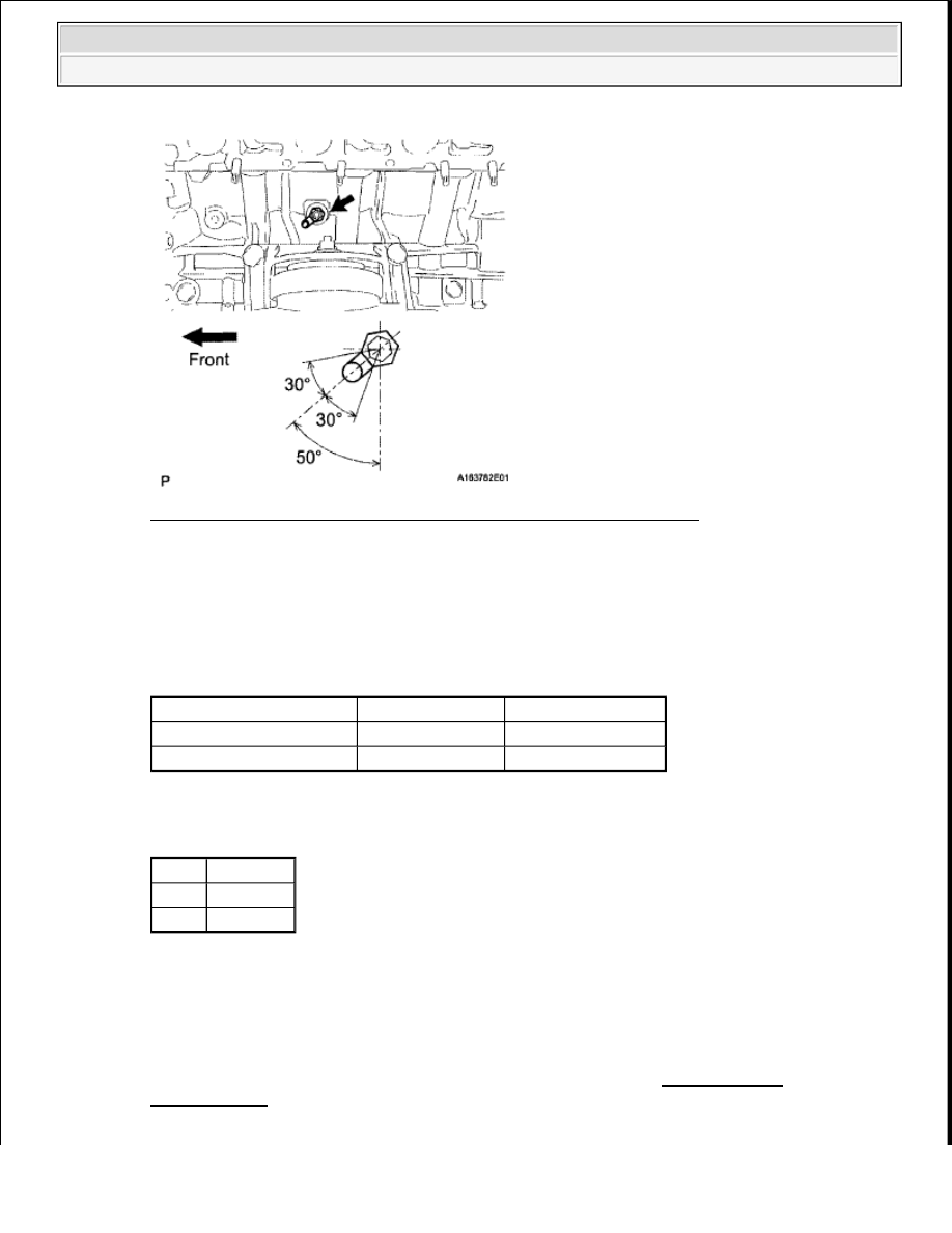
Fig. 53: Identifying Terminals Of D33 Or D34 A/F Sensor Connector
Courtesy of TOYOTA MOTOR SALES, U.S.A., INC.
b. Turn the ignition switch to ON.
c. Measure the voltage according to the value(s) in the table below.
Standard voltage
VOLTAGE SPECIFIED CONDITION
Result
RESULT REFERENCE
B: Go to step 5
A: Go to next step.
3. INSPECT INTEGRATION RELAY (A/F)
a. Remove the integration relay from the engine room relay block (see ON-VEHICLE
INSPECTION ).
b. Inspect the A/F fuse.
Tester Connection
Switch Condition Specified Condition
D33-2 (+B) - Body ground Ignition switch ON
11 to 14 V
D34-2 (+B) - Body ground Ignition switch ON
11 to 14 V
Result Proceed to
NG
A
OK
B
2009 Toyota Tundra
2009 ENGINE PERFORMANCE Engine Control System (3UR-FBE) - Tundra