Toyota Tundra. Manual - part 1468


  Index      Toyota     Toyota Tundra (2007-2010 year) - Service and Repair Manual


Search            copyright infringement  


Content   ..  1466  1467  1468  1469   ..


Toyota Tundra. Manual - part 1468


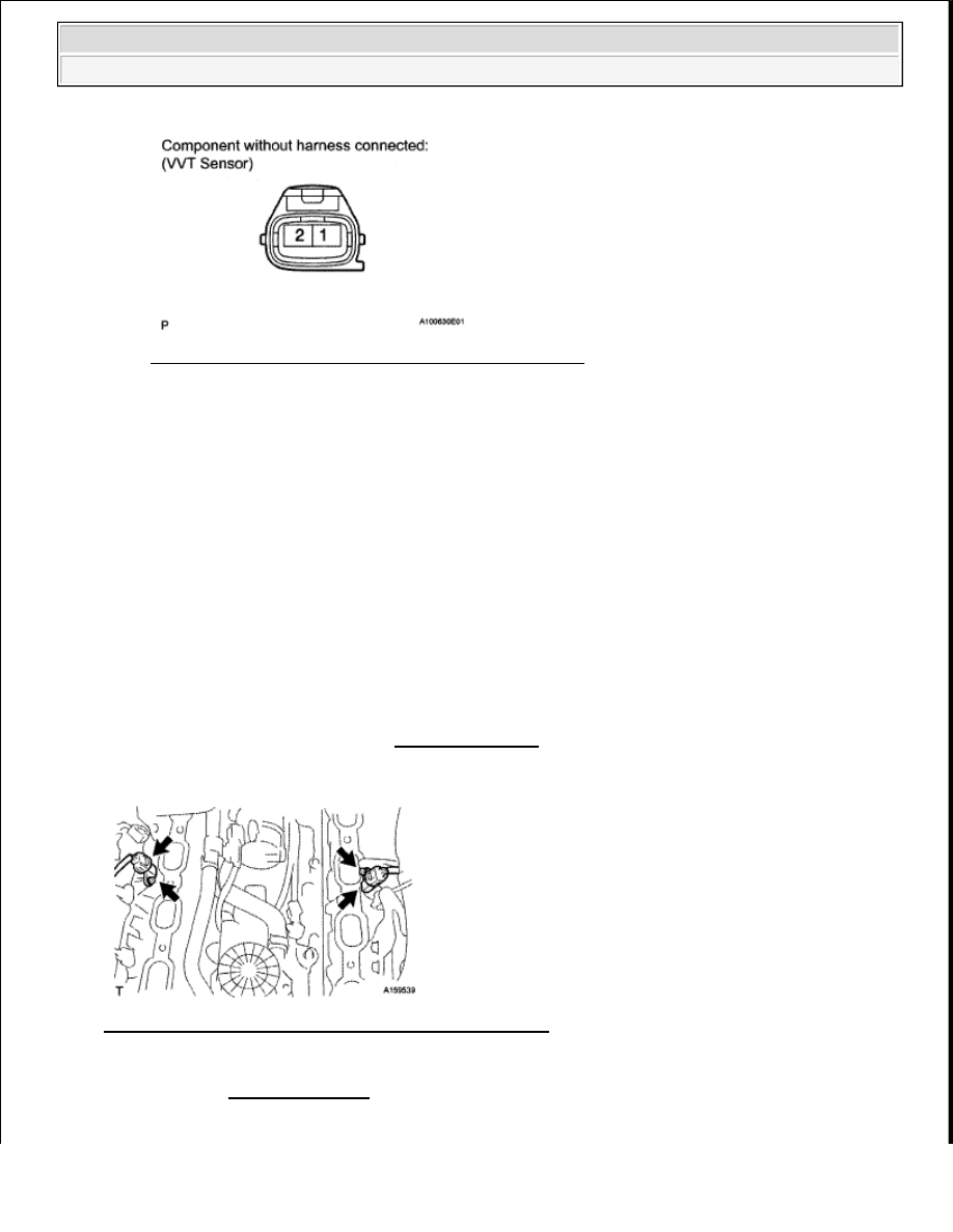
Fig. 362: Identifying VVT Sensor Connector Terminal 

If the resistance is not as specified, replace the sensor. 

INSTALLATION 

1. INSTALL VVT SENSOR 

a. Install the 2 sensors with the 2 bolt. 

Torque: 7.5 N*m (76 kgf*cm, 66 in.*lbf)  

b. Connect the 2 sensor connectors.  

2. INSTALL INTAKE MANIFOLD ASSEMBLY 

a. Install the intake manifold. (See INSTALLATION ).  

3. CONNECT CABLE TO NEGATIVE BATTERY TERMINAL 

Fig. 363: Identifying VVT Sensor Connector With Bolts 

NOTE:

In the table above, the terms "cold" and "hot" refer to the 
temperature of the sensor. "Cold" means approximately -10 to 50°C 
(14 to 122°F). "Hot" means approximately 50 to 100°C (122 to 212°F).

NOTE:

Some systems need to be initialized after the cable is reconnected. (See 
INITIALIZATION ).


2008 Toyota Tundra 

2008 ENGINE PERFORMANCE Engine Control System (2UZ-FE) - Tundra


CRANKSHAFT POSITION SENSOR 

COMPONENTS 

Fig. 364: Identifying Crankshaft Position Sensor Replacement Components With Torque Specifications 

REMOVAL 

1. DISCONNECT CABLE FROM NEGATIVE BATTERY TERMINAL 


2008 Toyota Tundra 

2008 ENGINE PERFORMANCE Engine Control System (2UZ-FE) - Tundra


2. REMOVE NO. 1 ENGINE UNDER COVER . (See COOLING SYSTEM ).  

3. REMOVE CRANKSHAFT POSITION SENSOR 

a. Disconnect the sensor connector.  

b. Remove the bolt and sensor. 

Fig. 365: Locating Crankshaft Position Sensor Connector & Bolt 

INSPECTION 

1. INSPECT CRANKSHAFT POSITION SENSOR 

a. Measure the resistance according to the value(s) in the table below. 

Standard resistance  

STANDARD RESISTANCE SPECIFICATION 

NOTE:

Some systems need to be initialized after the cable is reconnected. 
(See INITIALIZATION ).  

After the ignition switch is turned OFF, the navigation system 
requires approximately 90 seconds to record various types of 
memory and settings. As a result, after turning the ignition switch 
OFF, wait 90 seconds or more before disconnecting the cable from 
the negative (-) battery terminal.  

Tester Connection Condition Specified Condition

1 - 2

Cold

1630 to 2740 ohms

1 - 2

Hot

2065 to 3225 ohms


2008 Toyota Tundra 

2008 ENGINE PERFORMANCE Engine Control System (2UZ-FE) - Tundra


Fig. 366: Inspecting Crankshaft Position Sensor 

If the resistance is not as specified, replace the crankshaft position sensor. 

INSTALLATION 

1. INSTALL CRANKSHAFT POSITION SENSOR 

a. Install the sensor with the bolt. 

Torque: 6.5 N*m (65 kgf*cm, 58 in.*lbf)  

b. Connect the sensor connector.  

2. INSTALL NO. 1 ENGINE UNDER COVER . (See COOLING SYSTEM ).  

3. CONNECT CABLE TO NEGATIVE BATTERY TERMINAL 

Fig. 367: Locating Crankshaft Position Sensor Connector & Bolt 

ENGINE COOLANT TEMPERATURE SENSOR 

NOTE:

In the table above, the terms "cold" and "hot" refer to the 
temperature of the sensor. "Cold" means approximately -10 to 50°C 
(14 to 122°F). "Hot" means approximately 50 to 100°C (122 to 212°F).

NOTE:

Some systems need to be initialized after the cable is reconnected. (See 
INITIALIZATION ).


2008 Toyota Tundra 

2008 ENGINE PERFORMANCE Engine Control System (2UZ-FE) - Tundra


Content   ..  1466  1467  1468  1469   ..