Toyota Tundra. Manual - part 1449


  Index      Toyota     Toyota Tundra (2007-2010 year) - Service and Repair Manual


Search            copyright infringement  


Content   ..  1447  1448  1449  1450   ..


Toyota Tundra. Manual - part 1449


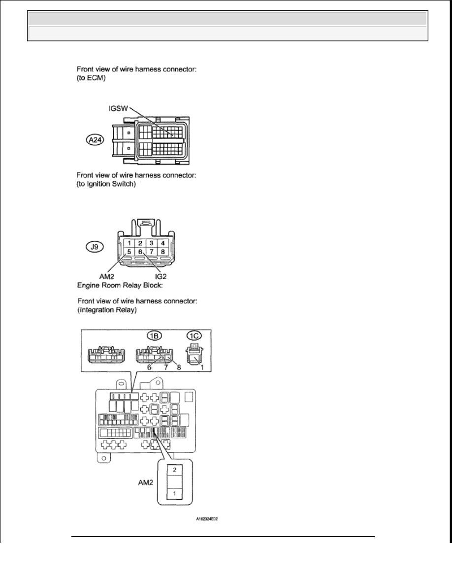
Fig. 282: Identifying A24 ECM & J9 Ignition Switch Connector With AM2 Fuse 


2008 Toyota Tundra 

2008 ENGINE PERFORMANCE Engine Control System (2UZ-FE) - Tundra


NG : REPAIR OR REPLACE HARNESS OR CONNECTOR  

OK : Go to Next Step  

6. INSPECT IGNITION SWITCH (See INSPECTION PROCEDURE ) 

NG : REPLACE IGNITION SWITCH . (See IGNITION SWITCH ). 

OK : Go to Next Step  

7. CHECK HARNESS AND CONNECTOR (INTEGRATION RELAY - ECM, BATTERY AND 

BODY GROUND) 

a. Disconnect the A24 ECM connector.  

b. Disconnect the cable from the battery positive terminal.  

c. Remove the integration relay from the engine room relay block.  

d. Disconnect the integration relay connector.  

e. Measure the resistance according to the value(s) in the table below. 

Standard resistance  

STANDARD RESISTANCE SPECIFICATION 

Tester Connection

Condition Specified Condition

A24-3 (+B) - 1B-4

Always

Below 1 ohms

A24-2 (+B2) - 1B-4

Always

Below 1 ohms

A24-34 (MREL) - 1B-2

Always

Below 1 ohms

1C-1 - Positive (+) battery cable

Always

Below 1 ohms

1B-3 - Body ground

Always

Below 1 ohms

A24-3 (+B) or 1B-4 - Body ground

Always

10 kohms or higher

A24-2 (+B2) or 1B-4 - Body ground

Always

10 kohms or higher

A24-34 (MREL) or 1B-2 - Body ground

Always

10 kohms or higher

1C-1 or Positive (+) battery cable - Body ground Always

10 kohms or higher


2008 Toyota Tundra 

2008 ENGINE PERFORMANCE Engine Control System (2UZ-FE) - Tundra


Fig. 283: Identifying A24 ECM Connector & Integration Relay 

NG : REPAIR OR REPLACE HARNESS OR CONNECTOR  

OK : REPAIR OR REPLACE ENGINE ROOM RELAY BLOCK  

VC OUTPUT CIRCUIT 

DESCRIPTION 

The ECM constantly generates 5 V power from the battery voltages supplied to the +B (BATT) terminal to 
operate the microprocessor. The ECM also provides this power to the sensors through the VC output circuit. 


2008 Toyota Tundra 

2008 ENGINE PERFORMANCE Engine Control System (2UZ-FE) - Tundra


Fig. 284: VC Output Circuit Diagram 

When the VC circuit is short-circuited, the microprocessor in the ECM and sensors that are supplied with power 
through the VC circuit are inactivated because the power is not supplied from the VC circuit. Under this 
condition, the system does not start up and the MIL does not illuminate even if the system malfunctions. 

HINT: 

Under normal conditions, the MIL is illuminated for several seconds when the ignition switch is first turned 
ON. The MIL goes off when the engine is started. 

WIRING DIAGRAM 


2008 Toyota Tundra 

2008 ENGINE PERFORMANCE Engine Control System (2UZ-FE) - Tundra


Content   ..  1447  1448  1449  1450   ..