Toyota Tundra. Manual - part 1445


  Index      Toyota     Toyota Tundra (2007-2010 year) - Service and Repair Manual


Search            copyright infringement  


Content   ..  1443  1444  1445  1446   ..


Toyota Tundra. Manual - part 1445
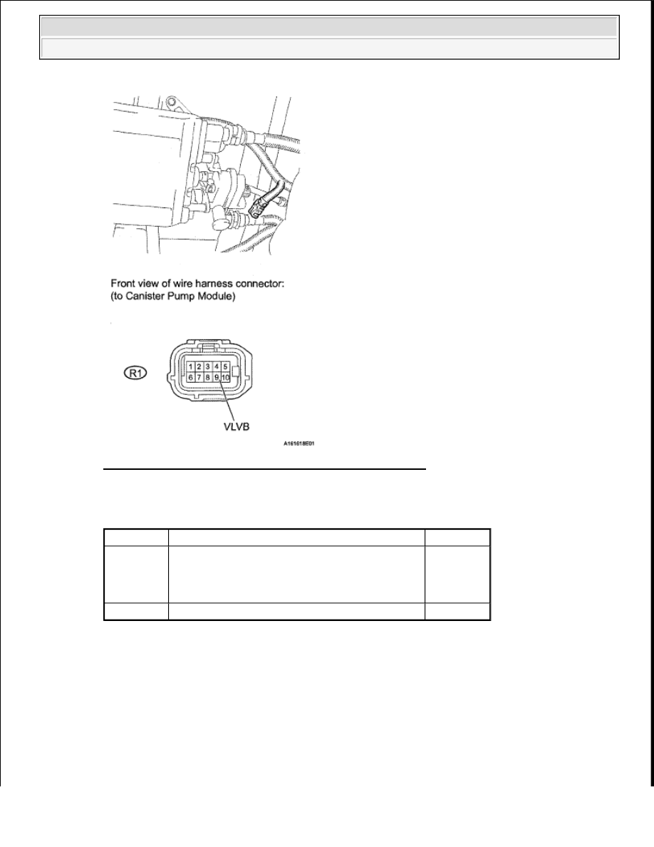


Fig. 268: Identifying R1 Canister Pump Module Connector 

Result  

RESULT REFERENCE 

B : Go to step 31 

A : Go to Next Step  

20. INSPECT CANISTER PUMP MODULE (VENT VALVE OPERATION) 

a. Turn the ignition switch off.  

b. Disconnect the R1 canister pump module connector.  

c. Apply the battery voltage to 9 (VLVB) and 8 (VGND) terminals of the canister pump module.  

d. Touch the canister pump module to confirm the vent valve operation. 

Test Result

Suspected Trouble Area

Proceed To

11 to 14 V

1. Wire harness between vent valve and ECM 

2. Vent valve  

3. ECM  

A

Below 3 V Power source wire harness of vent valve

B


2008 Toyota Tundra 

2008 ENGINE PERFORMANCE Engine Control System (2UZ-FE) - Tundra


Fig. 269: Identifying Terminal (VLVB) & (VGND) Of Canister Pump Module 

Result  

RESULT REFERENCE 

B : Go to step 29 

A : Go to Next Step  

21. CHECK HARNESS AND CONNECTOR (ECM - CANISTER PUMP MODULE) 

a. Disconnect the A24 ECM connector.  

b. Disconnect the R1 canister pump module connector. 

Test Result

Suspected Trouble Area

Proceed To

Operating

1. Wire harness between vent valve and ECM 

2. ECM  

A

Not operating Vent valve

B


2008 Toyota Tundra 

2008 ENGINE PERFORMANCE Engine Control System (2UZ-FE) - Tundra


Fig. 270: Identifying A24 ECM & R1 Canister Pump Module Connectors 

c. Measure the resistance between VPMP terminal of the ECM connector and VGND terminal of the 

canister pump module connector. 

Result  

RESULT REFERENCE 

A : Go to step 34 

B : Go to step 31 

22. PERFORM ACTIVE TEST USING TECHSTREAM (VACUUM PUMP (ALONE)) 

a. Turn the ignition switch off.  

b. Disconnect the R1 canister pump module connector.  

c. Turn the ignition switch to ON.  

d. Enter the following menus: Powertrain/Engine and ECT/Active Test/Activate the Vacuum Pump.  

e. Measure the voltage between MTRB terminal 1 of the canister pump module connector and the 

body ground when the leak detection pump is turned ON and OFF using the Techstream. 

Test Result

Suspected Trouble Area

Proceed To

Below 1 ohms

ECM

A

10 kohms or higher Wire harness between ECM and canister pump module

B


2008 Toyota Tundra 

2008 ENGINE PERFORMANCE Engine Control System (2UZ-FE) - Tundra


Fig. 271: Identifying R1 Canister Pump Module Connector 

Result  

RESULT REFERENCE 

B : Go to step 24 

A : Go to Next Step  

Test Result

Suspected Trouble Area

Proceed 

To

Below 3 V when OFF 
9 to 14 V when ON

1. Wire harness between leak detection pump and body 

ground  

2. Leak detection pump  

A

Below 3 V when OFF and 
ON

1. Wire harness between leak detection pump and 

ECM  

2. ECM  

B

9 to 14 V when OFF and 
ON

1. Wire harness between leak detection pump and 

ECM  

2. ECM  

B


2008 Toyota Tundra 

2008 ENGINE PERFORMANCE Engine Control System (2UZ-FE) - Tundra


Content   ..  1443  1444  1445  1446   ..