Toyota Tundra. Manual - part 1418


  Index      Toyota     Toyota Tundra (2007-2010 year) - Service and Repair Manual


Search            copyright infringement  


Content   ..  1416  1417  1418  1419   ..


Toyota Tundra. Manual - part 1418
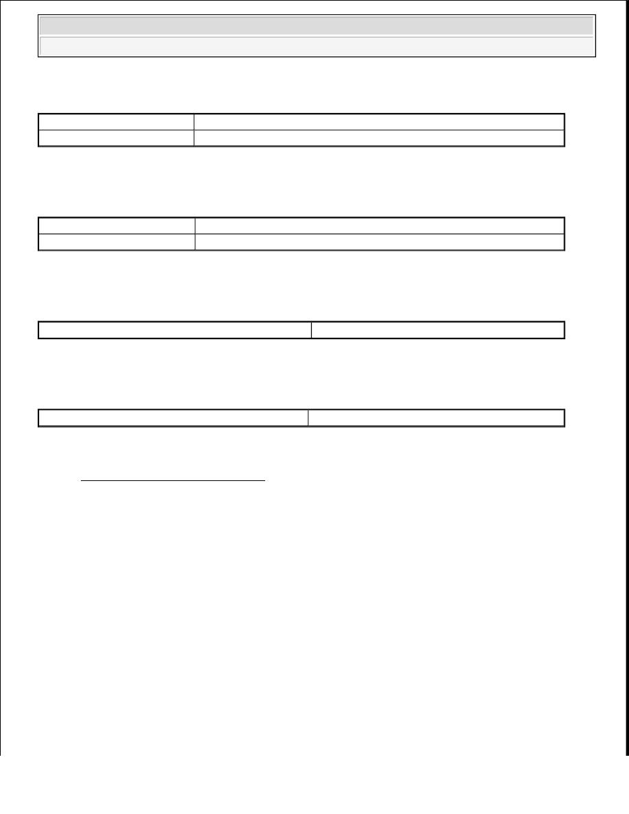


TYPICAL MALFUNCTION THRESHOLDS - SENSOR VOLTAGE DETECTION MONITOR (LEAN 
SIDE MALFUNCTION P2195 AND P2197)
 

Sensor voltage detection monitor (Rich side malfunction P2196 and P2198):  

TYPICAL MALFUNCTION THRESHOLDS - SENSOR VOLTAGE DETECTION MONITOR (RICH 
SIDE MALFUNCTION P2196 AND P2198)
 

Sensor current detection monitor (High side malfunction P2195 and P2197):  

TYPICAL MALFUNCTION THRESHOLDS - SENSOR CURRENT DETECTION MONITOR (HIGH 
SIDE MALFUNCTION P2195 AND P2197)
 

Sensor current detection monitor (Rich side malfunction P2196 and P2198):  

TYPICAL MALFUNCTION THRESHOLDS - SENSOR CURRENT DETECTION MONITOR (RICH 
SIDE MALFUNCTION P2196 AND P2198)
 

MONITOR RESULT 

Refer to CHECKING MONITOR STATUS . 

WIRING DIAGRAM 

Rear HO2S voltage

Rises from less than 0.21 V to 0.59 V or higher

A/F sensor voltage

Higher than 3.8 V

Rear HO2S voltage

Falls from 0.59 V or higher to less than 0.21 V

A/F sensor voltage

Less than 2.8 V

A/F sensor current

3.6 mA or higher

A/F sensor current

Less than 1.4 mA


2008 Toyota Tundra 

2008 ENGINE PERFORMANCE Engine Control System (2UZ-FE) - Tundra


Fig. 219: Oxygen (A/F) Sensor Signal Stuck - Wiring Diagram 

CONFIRMATION DRIVING PATTERN 

This confirmation driving pattern is used in the "PERFORM CONFIRMATION DRIVING PATTERN" 
procedure of the following diagnostic troubleshooting procedure. 

CAUTION: Strictly observe posted speed limits, traffic laws, and road conditions 

when performing these drive patterns.


2008 Toyota Tundra 

2008 ENGINE PERFORMANCE Engine Control System (2UZ-FE) - Tundra


Fig. 220: Vehicle Speed Graph 

Fig. 221: Engine Speed Graph 

a. Connect the Techstream to the DLC3.  

b. Turn the ignition switch to ON.  

c. Turn the Techstream ON.  

d. Clear DTCs. (See DTC CHECK/CLEAR ).  

e. Start the engine, and warm it up until the ECT reaches 75°C (167°F) or higher.  

f. Enter the following menus: Powertrain/Engine and ECT/Data List/All Data/Idle Fuel Cut.  

g. Drive the vehicle at between 60 km/h (38 mph) and 120 km/h (75 mph) for at least 10 minutes.  

h. Change the transmission to 2nd gear.  


2008 Toyota Tundra 

2008 ENGINE PERFORMANCE Engine Control System (2UZ-FE) - Tundra


i. Drive the vehicle at the proper vehicle speed to perform fuel-cut operation. 

HINT: 

Fuel-cut is performed when the following conditions are met: 

Accelerator pedal fully released.  

Engine speed is 2500 RPM or more (fuel injection returns at 1000 RPM).  

j. Accelerate the vehicle to 64 km/h (40 mph) or more by depressing the accelerator pedal for at least 10 

seconds.  

k. Soon after performing step (j) above, release the accelerator pedal for at least 4 seconds without 

depressing the brake pedal, in order to execute fuel-cut control.  

l. Allow the vehicle to decelerate until the vehicle speed declines to less than 10 km/h (6 mph).  

m. Repeat steps (g) through (j) above at least 3 times in one driving cycle.  

HINT: 

Completion of all O2S (A/F) Monitor id required to change the value in Data List. 

INSPECTION PROCEDURE 

HINT: 

Although the DTC titles say oxygen sensor, these DTCs relate to the Air-Fuel Ratio (A/F) sensor.  

Sensor 1 refers to the sensor mounted in front of the Three-Way Catalytic Converter (TWC) and located 
near the engine assembly.  

DTC P2A00 may be set when the air-fuel ratio is stuck rich or lean.  

Read freeze frame data using the Techstream. Freeze frame data records the engine condition when 
malfunctions are detected. When troubleshooting, freeze frame data can help determine if the vehicle was 
moving or stationary, if the engine was warmed up or not, if the air-fuel ratio was lean or rich, and other 
data from the time the malfunction occurred.  

A low A/F sensor voltage could be caused by a rich air-fuel mixture. Check for conditions that would 
cause the engine to run rich.  

A high A/F sensor voltage could be caused by a lean air-fuel mixture. Check for conditions that would 
cause the engine to run lean.  

HINT: 

Malfunctioning areas can be identified by performing the Control the Injection Volume for A/F Sensor function 
provided in the Active Test. The Control the Injection Volume for A/F Sensor function can help to determine 
whether the Air-fuel Ratio (A/F) sensor, Heated Oxygen (HO2) sensor and other potential trouble areas are 
malfunctioning. 

The following instructions describe how to conduct the Control the Injection Volume for A/F Sensor operation 
using the Techstream. 


2008 Toyota Tundra 

2008 ENGINE PERFORMANCE Engine Control System (2UZ-FE) - Tundra


Content   ..  1416  1417  1418  1419   ..