Content .. 1403 1404 1405 1406 ..
Toyota Tundra. Manual - part 1405
COMPONENT OPERATING RANGE
COMPONENT OPERATING RANGE
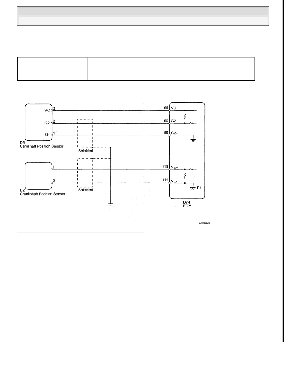
WIRING DIAGRAM
Fig. 196: Camshaft Position Sensor - Wiring Diagram
INSPECTION PROCEDURE
HINT:
Read freeze frame data using the Techstream. Freeze frame data records the engine conditions when
malfunctions are detected. When troubleshooting, freeze frame data can help determine if the vehicle was
running or stopped, if the engine was warmed up or not, if the air fuel ratio was lean or rich, and other data from
the time the malfunction occurred.
1. INSPECT CAMSHAFT POSITION SENSOR (SENSOR POWER SOURCE)
a. Disconnect the D5 camshaft position sensor connector.
b. Turn the ignition switch to ON.
c. Measure the voltage according to the value(s) in the table below.
Standard voltage
Camshaft position sensor
signal
Camshaft position sensor voltage fluctuates when the camshaft
rotates
3 signals per revolution of crankshaft
2008 Toyota Tundra
2008 ENGINE PERFORMANCE Engine Control System (2UZ-FE) - Tundra