Content .. 1330 1331 1332 1333 ..
Toyota Tundra. Manual - part 1332
In the VVT (Variable Valve Timing) system, the appropriate intake valve open and close timing is controlled by
the ECM. The ECM performs intake valve control by performing the following: 1) controlling the camshaft and
camshaft timing oil control valve, and operating the camshaft timing gear; and 2) changing the relative positions
of the gaps between the camshaft and crankshaft.
DTC DETECTION CONDITION AND TROUBLE AREA
MONITOR DESCRIPTION
To monitor the correlation of the intake camshaft position and crankshaft position, the ECM checks the VVT
learning value while the engine is idling. The VVT learning value is calibrated based on the camshaft position
and crankshaft position. The intake valve timing is set to the most retarded angle while the engine is idling. If
the VVT learning value is out of the specified range in consecutive driving cycles, the ECM illuminates the
MIL and sets the DTC P0016 (for bank 1) or P0018 (for bank 2).
MONITOR STRATEGY
MONITOR STRATEGY
TYPICAL ENABLING CONDITIONS
TYPICAL ENABLING CONDITIONS
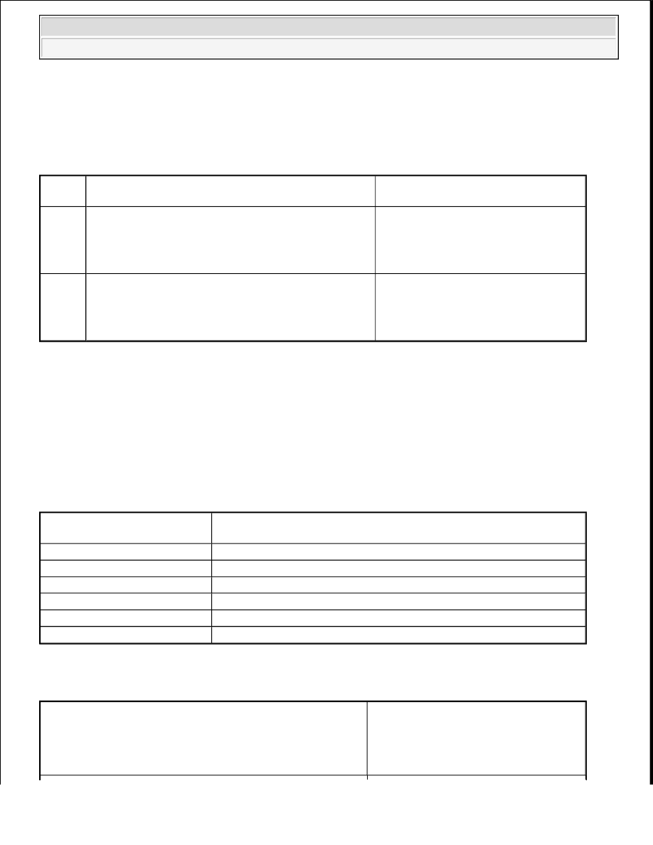
DTC
Code
DTC Detection Condition
Trouble Area
P0016
Deviation in crankshaft position sensor signal and VVT
sensor 1 (intake camshaft for bank 1) signal (2 trip
detection logic)
Mechanical system (Timing belt
has jumped tooth or belt
stretched)
ECM
P0018
Deviation in crankshaft position sensor signal and VVT
sensor 2 (intake camshaft for bank 2) signal (2 trip
detection logic)
Mechanical system (Timing belt
has jumped tooth or belt
stretched)
ECM
Related DTCs
P0016: Camshaft timing misalignment at idling (bank 1 intake side)
P0018: Camshaft timing misalignment at idling (bank 2 intake side)
Required Sensors/Components
VVT actuator
Required Sensors/Components
Camshaft position sensor, Crankshaft position sensor
Frequency of Operation
Once per driving cycle
Duration
Within 1 minute
MIL Operation
2 driving cycles
Sequence of Operation
None
Monitor runs whenever following DTCs not present
P0011 (VVT System 1 - Advance)
P0012 (VVT System 1 - Retard)
P0021 (VVT System 2 - Advance)
P0022 (VVT System 2 - Retard)
P0115 - P0118 (ECT sensor)
2008 Toyota Tundra
2008 ENGINE PERFORMANCE Engine Control System (2UZ-FE) - Tundra