Toyota Tundra. Manual - part 1305


  Index      Toyota     Toyota Tundra (2007-2010 year) - Service and Repair Manual


Search            copyright infringement  


Content   ..  1303  1304  1305  1306   ..


Toyota Tundra. Manual - part 1305
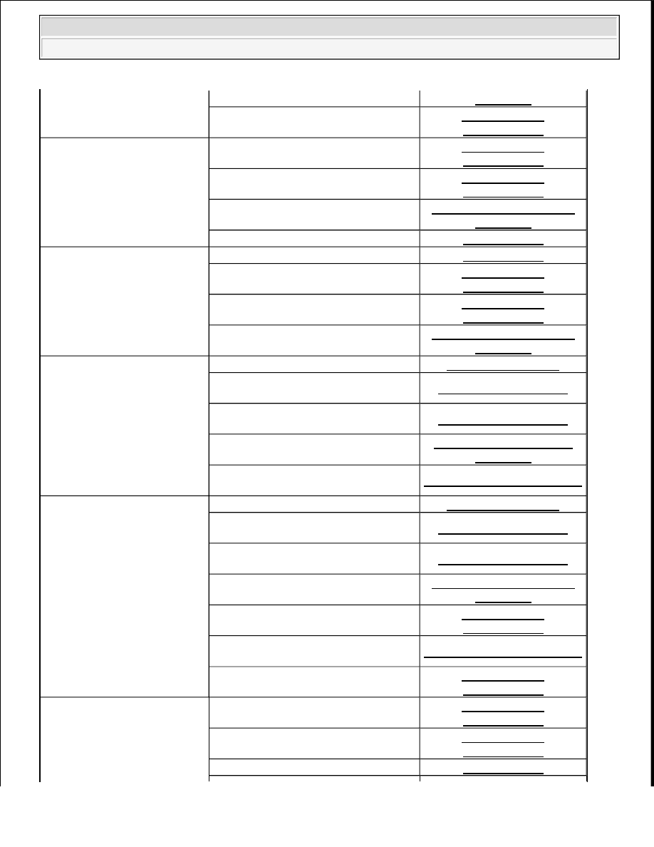


Engine cranks normally but 
difficult to start

CIRCUIT

Compression

ON-VEHICLE 

INSPECTION 

Difficult to start with cold 
engine

Ignition system

ON-VEHICLE 

INSPECTION 

Spark plug

ON-VEHICLE 

INSPECTION 

Fuel pump control circuit

FUEL PUMP CONTROL 

CIRCUIT

Injector

INSPECTION 

Difficult to start with warm 
engine

Injector

INSPECTION 

Ignition system

ON-VEHICLE 

INSPECTION 

Spark plug

ON-VEHICLE 

INSPECTION 

Fuel pump control circuit

FUEL PUMP CONTROL 

CIRCUIT

High engine idle speed

Electronic throttle control system

THROTTLE BODY

A/C signal circuit (for Automatic Air 
Conditioning System)

TERMINALS OF ECU 

A/C signal circuit (for Manual Air 
Conditioning System)

TERMINALS OF ECU 

ECM power source circuit

ECM POWER SOURCE 

CIRCUIT

Acoustic Control Induction System 
(ACIS)

ACIS CONTROL CIRCUIT

Low engine idle speed (Poor 
idling)

Electronic throttle control system

THROTTLE BODY

A/C signal circuit (for Automatic Air 
Conditioning System)

TERMINALS OF ECU 

A/C signal circuit (for Manual Air 
Conditioning System)

TERMINALS OF ECU 

Fuel pump control circuit

FUEL PUMP CONTROL 

CIRCUIT

Air induction system

ON-VEHICLE 

INSPECTION 

Acoustic Control Induction System 
(ACIS)

ACIS CONTROL CIRCUIT

PCV hose

ON-VEHICLE 

INSPECTION 

Compression

ON-VEHICLE 

INSPECTION 

Spark plug

ON-VEHICLE 

INSPECTION 

Injector

INSPECTION 


2008 Toyota Tundra 

2008 ENGINE PERFORMANCE Engine Control System (2UZ-FE) - Tundra


Rough idling

Ignition system

ON-VEHICLE 

INSPECTION 

Fuel pump control circuit

FUEL PUMP CONTROL 

CIRCUIT

Electronic throttle control system

THROTTLE BODY

Air induction system

ON-VEHICLE 

INSPECTION 

Acoustic Control Induction System 
(ACIS)

ACIS CONTROL CIRCUIT

PCV hose

ON-VEHICLE 

INSPECTION 

Mass air flow meter

MASS AIR FLOW METER

Idle hunting

Electronic throttle control system

THROTTLE BODY

Air induction system

ON-VEHICLE 

INSPECTION 

ECM power source circuit

ECM POWER SOURCE 

CIRCUIT

Acoustic Control Induction System 
(ACIS)

ACIS CONTROL CIRCUIT

Hesitation/Poor acceleration

Fuel pump control circuit

FUEL PUMP CONTROL 

CIRCUIT

Spark plug

ON-VEHICLE 

INSPECTION 

Ignition system

ON-VEHICLE 

INSPECTION 

Injector

INSPECTION 

Mass air flow meter

MASS AIR FLOW METER

Electronic throttle control system

THROTTLE BODY

Air induction system

ON-VEHICLE 

INSPECTION 

Compression

ON-VEHICLE 

INSPECTION 

Surging (Poor driveability)

Spark plug

ON-VEHICLE 

INSPECTION 

Fuel pump control circuit

FUEL PUMP CONTROL 

CIRCUIT

Ignition system

ON-VEHICLE 

INSPECTION 

Injector

INSPECTION 

Mass air flow meter

MASS AIR FLOW METER

Variable valve timing system

CAMSHAFT OIL 

CONTROL VALVE

Compression

ON-VEHICLE 

INSPECTION 


2008 Toyota Tundra 

2008 ENGINE PERFORMANCE Engine Control System (2UZ-FE) - Tundra


TERMINALS OF ECM 

1. CHECK ECM 

Fig. 15: Identifying Terminals Of ECM 

a. Measure the voltage according to the value(s) in the table below. 

HINT: 

Engine stalls soon after starting

Fuel pump control circuit

FUEL PUMP CONTROL 

CIRCUIT

Spark plug

ON-VEHICLE 

INSPECTION 

Ignition system

ON-VEHICLE 

INSPECTION 

Injector

INSPECTION 

Variable valve timing system

CAMSHAFT OIL 

CONTROL VALVE

Electronic throttle control system

THROTTLE BODY

Air induction system

ON-VEHICLE 

INSPECTION 

PCV hose

ON-VEHICLE 

INSPECTION 

Compression

ON-VEHICLE 

INSPECTION 

Engine stalls only during A/C 
operation

A/C signal circuit (for Automatic Air 
Conditioning System)

TERMINALS OF ECU 

A/C signal circuit (for Manual Air 
Conditioning System)

TERMINALS OF ECU 

ECM

TERMINALS OF ECM

Unable/difficult to refuel

Refueling valve (canister)

-


2008 Toyota Tundra 

2008 ENGINE PERFORMANCE Engine Control System (2UZ-FE) - Tundra


The standard normal voltage between each pair of ECM terminals is shown in the table below. The 
appropriate conditions for checking each pair of terminals are also indicated. The result of checks 
should be compared with the standard normal voltage for that pair of terminals, displayed in the 
Specified Condition column. The illustration above can be used as a reference to identify the ECM 
terminal locations. 

CONNECTOR TERMINAL WIRING COLOR REFERENCE 

Terminal No. 

(Symbols)

Wiring 

Color

Terminal Description

Condition

Specified 

Condition

A24-1 (BATT) 

- D74-81 (E1)

L - BR

Battery (for measuring 
battery voltage and for 
ECM memory)

Always

11 to 14 V

D74-41 (+BM) 

- D74-81 (E1)

P - BR

Power source of throttle 
actuator

Always

11 to 14 V

A24-28 

(IGSW) - D74-

81 (E1)

LG - BR Ignition switch

Ignition switch ON

11 to 14 V

A24-3 (+B) - 

D74-81 (E1)

GR - BR Power source of ECM

Ignition switch ON

11 to 14 V

A24-2 (+B2) - 

D74-81 (E1)

GR - BR Power source of ECM

Ignition switch ON

11 to 14 V

D74-58 (OC1+) 
- D74-57 (OC1-

)

B-B-L

Camshaft timing oil 
control valve (OCV)

Ignition switch ON

Pulse generation 

(See awaveform 

1)

D74-52 (OC2+) 
- D74-51 (OC2-

)

L-B - R-B

Camshaft timing oil 
control valve (OCV) 
(Intake side (for bank 2))

Ignition switch ON

Pulse generation 

(See awaveform 

1)

A24-34 

(MREL) - D74-

81 (E1)

W - BR EFI relay

Ignition switch ON

11 to 14 V

D74-74 (VG) - 

D74-75 (E2G)

L-Y - G-W Mass air flow meter

Idling, Shift lever 
position P or N, A/C 
switch OFF

0.5 to 3.0 V

D74-73 (THA) 

- D74-97 

(ETHW)

Y-B - BR

Intake air temperature 
sensor

Idling, Intake air 
temperature 20°C (68°F)

0.5 to 3.4 V

D74-76 (THW) 

- D74-97 

(ETHW)

G-B - BR

Engine coolant 
temperature sensor

Idling, Engine coolant 
temperature 80°C (176°
F)

0.2 to 1.0 V

D74-80 

(VCTA) - D74-

79 (ETA)

L - Y

Power source of throttle 
position sensor (specific 
voltage)

Ignition switch ON

4.5 to 5.5 V

D74-78 

(VTA1) - D74-

79 (ETA)

R - Y-Y

Throttle position sensor 
(for engine control)

Ignition switch ON, 
Throttle valve fully 
closed

0.5 to 1.2 V

Ignition switch ON, 


2008 Toyota Tundra 

2008 ENGINE PERFORMANCE Engine Control System (2UZ-FE) - Tundra


Content   ..  1303  1304  1305  1306   ..