Toyota Tundra. Manual - part 1232


  Index      Toyota     Toyota Tundra (2007-2010 year) - Service and Repair Manual


Search            copyright infringement  


Content   ..  1230  1231  1232  1233   ..


Toyota Tundra. Manual - part 1232


malfunctions, is set, the ECM enters fail-safe mode. During fail-safe mode, the ECM cuts the current to the 
throttle actuator, and the throttle valve is returned to a 6° throttle angle by the return spring. The ECM then 
adjusts the engine output by controlling the fuel injection (intermittent fuel-cut) and ignition timing, in 
accordance with the accelerator pedal opening angle, to allow the vehicle to continue running at a minimal 
speed. If the accelerator pedal is depressed firmly and gently, the vehicle can be driven slowly. Fail-safe mode 
continues until a pass condition is detected, and the ignition switch is then turned OFF. 

WIRING DIAGRAM 

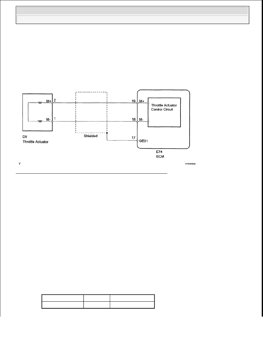
Fig. 187: Throttle Actuator Control Motor Circuit - Wiring Diagram 

INSPECTION PROCEDURE 

HINT: 

Read freeze frame data using the Techstream. Freeze frame data records the engine condition when 
malfunctions are detected. When troubleshooting, freeze frame data can help determine if the vehicle was 
moving or stationary, if the engine was warmed up or not, if the air-fuel ratio was lean or rich, and other 
data from the time the malfunction occurred.  

The throttle actuator current (Throttle Motor Current) and the throttle actuator duty ratio (Throttle Motor 
Open Duty/Throttle Motor Close Duty) can be read using the Techstream. However, the ECM shuts off 
the throttle actuator current when the ETCS malfunctions.  

1. INSPECT THROTTLE BODY (RESISTANCE OF THROTTLE ACTUATOR) 

a. Disconnect the D9 throttle body connector.  

b. Measure the resistance according to the value (s) in the table below. 

Standard resistance  

TESTER CONNECTION SPECIFIED CONDITION 

Tester Connection Condition Specified Condition

2 (M+) - 1 (M-)

20°C (68°F)

0.3 to 100 ohms


2008 Toyota Tundra 

2008 ENGINE PERFORMANCE Engine Control System (1GR-FE) - Tundra


NG : REPLACE THROTTLE BODY (See REMOVAL ) 

Fig. 188: Identifying D9 Throttle Body Connector Terminals 

OK : Go to next step.  

2. CHECK HARNESS AND CONNECTOR (THROTTLE ACTUATOR - ECM) 

a. Disconnect the D9 throttle body connector.  

b. Disconnect the D74 ECM connector.  

c. Measure the resistance according to the value (s) in the table below. 

Standard resistance (Check for open)  

TESTER CONNECTION SPECIFIED CONDITION 

Standard resistance (Check for short)  

TESTER CONNECTION SPECIFIED CONDITION 

NG : REPAIR OR REPLACE HARNESS OR CONNECTOR  

Tester Connection

Condition Specified Condition

D9-2 (M+) - D74-19 (M+) Always

Below 1 ohms

D9-1 (M-) - D74-18 (M-)

Always

Below 1 ohms

Tester Connection

Condition Specified Condition

D9-2 (M+) or D74-19 (M+) - Body ground Always

10 kohms or higher

D9-1 (M-) or D74-18 (M-) - Body ground

Always

10 kohms or higher


2008 Toyota Tundra 

2008 ENGINE PERFORMANCE Engine Control System (1GR-FE) - Tundra


Fig. 189: Identifying D9 Throttle Body Connector & D74 ECM Connector Terminals 

OK : Go to next step.  

3. INSPECT THROTTLE BODY (VISUALLY CHECK THROTTLE VALVE) 

a. Check for foreign objects between the throttle valve and the housing.  

NG : REMOVE FOREIGN OBJECT AND CLEAN THROTTLE BODY  

OK : Go to next step.  

4. INSPECT THROTTLE VALVE 

a. Check if the throttle valve opens and closes smoothly.  

NG : REPLACE THROTTLE BODY (See REMOVAL ) 

OK : REPLACE ECM (See REMOVAL ) 

DTC P2111 THROTTLE ACTUATOR CONTROL SYSTEM - STUCK OPEN; DTC P2112 
THROTTLE ACTUATOR CONTROL SYSTEM - STUCK CLOSED 

SYSTEM DESCRIPTION 

The throttle actuator is operated by the ECM, and opens and closes the throttle valve using gears. The opening 
angle of the throttle valve is detected by the Throttle Position (TP) sensor, which is mounted on the throttle 
body. The TP sensor provides feedback to the ECM. This feedback allows the ECM to appropriately control the 
throttle actuator and monitor the throttle opening angle as the ECM responds to driver inputs. 


2008 Toyota Tundra 

2008 ENGINE PERFORMANCE Engine Control System (1GR-FE) - Tundra


HINT: 

This ETCS (Electronic Throttle Control System) does not use a throttle cable. 

DTC TROUBLE DETECTION CONDITION CHART 

MONITOR DESCRIPTION 

The ECM determines that there is a malfunction in the ETCS when the throttle valve remains at a fixed angle 
despite a high drive current from the ECM. The ECM illuminates the MIL and sets a DTC. If the malfunction is 
not repaired successfully, a DTC is set when the accelerator pedal is fully depressed and released quickly (to 
fully open and close the throttle valve) after the engine is next started. 

MONITOR STRATEGY 

MONITOR STRATEGY 

TYPICAL ENABLING CONDITIONS 

All:  

TYPICAL ENABLING CONDITIONS 

P2111 (Throttle actuator stuck open)  

DTC No.

DTC Detection Condition

Trouble Area

P2111 ECM signals throttle actuator to close, but stuck (1 trip detection logic)

Throttle actuator 

Throttle body  

Throttle valve  

ECM  

P2112 ECM signals throttle actuator to open, but stuck (1 trip detection logic)

Throttle actuator 

Throttle body  

Throttle valve  

ECM  

Related DTCs

P2111: Throttle actuator stuck open 
P2112: Throttle actuator stuck closed

Required Sensors/Components (Main)

Throttle actuator

Required Sensors/Components (Related)

-

Frequency of Operation

Continuous

Duration

0.5 seconds

MIL Operation

Immediate

Sequence of Operation

None

Monitor runs whenever following DTCs are not present

None


2008 Toyota Tundra 

2008 ENGINE PERFORMANCE Engine Control System (1GR-FE) - Tundra


Content   ..  1230  1231  1232  1233   ..