Content .. 1211 1212 1213 1214 ..
Toyota Tundra. Manual - part 1213
c. Measure the resistance according to the value(s) in the table below.
Standard resistance
TESTER CONNECTION SPECIFIED CONDITION
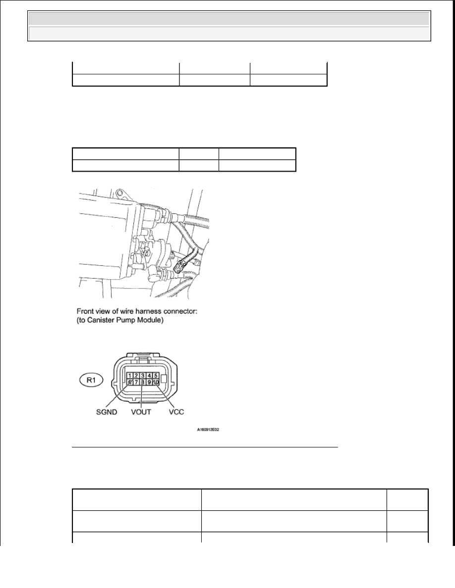
Fig. 159: Identifying R1 Canister Pump Module Connector Terminals
Result
RESULT CHART
R1-4 (VCC) - Body ground Ignition switch ON
4.5 to 5.5 V
R1-3 (VOUT) - Body ground Ignition switch ON
4.5 to 5.5 V
Tester Connection
Condition Specified Condition
R1-2 (SGND) - Body ground Always
100 ohms or less
Test Result
Suspected Trouble Area
Proceed
To
Voltage and resistance within
standard ranges
Open in canister pressure sensor circuit
A
2008 Toyota Tundra
2008 ENGINE PERFORMANCE Engine Control System (1GR-FE) - Tundra