Toyota Tundra. Manual - part 1066


  Index      Toyota     Toyota Tundra (2007-2010 year) - Service and Repair Manual


Search            copyright infringement  


Content   ..  1064  1065  1066  1067   ..


Toyota Tundra. Manual - part 1066


b. Measure each spider bearing's axial play by turning the yoke while holding the shaft tightly. 

Maximum bearing axial play:  

0.05 mm (0.00197 in.)  

Fig. 114: Inspecting Propeller Shaft Universal Joint Spider Bearing 
Courtesy of TOYOTA MOTOR SALES, U.S.A., INC. 

INSTALLATION 

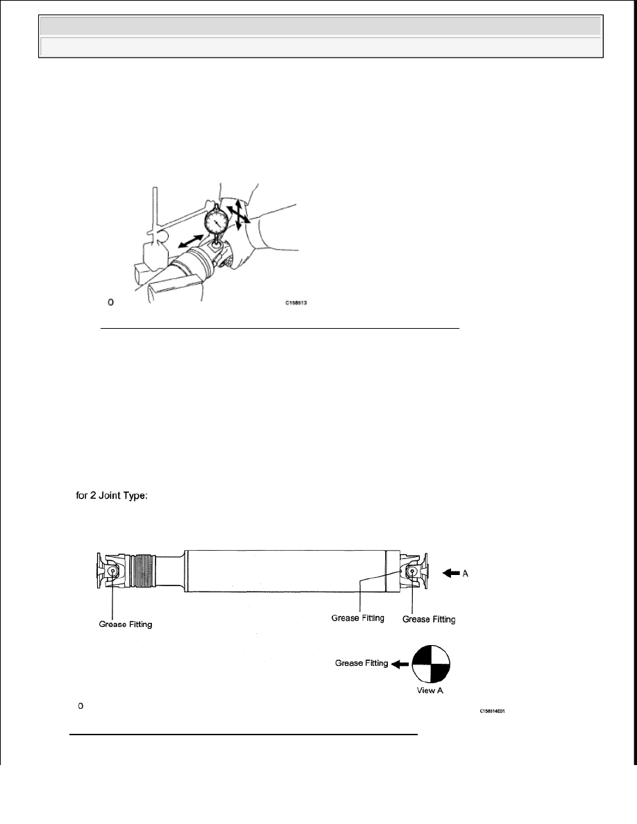
1. INSTALL PROPELLER SHAFT ASSEMBLY (for 2 Joint Type) 

HINT: 

When replacing the spider bearing, make sure that the grease fitting assembly hole is facing in the 
direction shown in the illustration. 

Fig. 115: Identifying Propeller Shaft Assembly (For 2 Joint Type) 
Courtesy of TOYOTA MOTOR SALES, U.S.A., INC. 


2009 Toyota Tundra 

2009 DRIVELINE/AXLES Propeller Shaft - Tundra


a. Align the matchmarks on the propeller shaft flange and differential flange. 

Fig. 116: Identifying Matchmarks On Propeller Shaft Flange And Differential Flange 
Courtesy of TOYOTA MOTOR SALES, U.S.A., INC. 

b. Install the propeller shaft to the differential side with the 4 bolts and 4 nuts. 

Torque: 70 N*m (714 kgf*cm, 52 ft.*lbf)  

c. Align the matchmarks on the propeller shaft flange and transfer flange. 

Fig. 117: Identifying Matchmarks On Propeller Shaft Flange And Transfer Flange 
Courtesy of TOYOTA MOTOR SALES, U.S.A., INC. 

d. Install the propeller shaft to the transfer side with the 4 nuts. 

Torque: 70 N*m (714 kgf*cm, 52 ft.*lbf)  

2. MEASURE TRANSFER AND DIFFERENTIAL FLANGE ANGLE (for 3 Joint Type) 

HINT: 

NOTE:

Perform the inspection on a level surface.  

Perform the inspection with the vehicle empty.  

Perform the inspection with all wheels on the ground. 


2009 Toyota Tundra 

2009 DRIVELINE/AXLES Propeller Shaft - Tundra


As the transfer and rear differential flange angles are necessary when measuring the installation angle of 
the propeller shaft, measure the angle of the transfer and rear differential flange before installing the 
propeller shaft. 

a. Using SST, measure and record the angle of the transfer flange (A). 

SST 09370-50010  

Fig. 118: Measuring Angle Of Transfer Flange 
Courtesy of TOYOTA MOTOR SALES, U.S.A., INC. 

b. Using SST, measure and record the angle of the rear differential flange (B). 

SST 09370-50010  

Fig. 119: Rear Differential Flange Angle 
Courtesy of TOYOTA MOTOR SALES, U.S.A., INC. 


2009 Toyota Tundra 

2009 DRIVELINE/AXLES Propeller Shaft - Tundra


3. TEMPORARILY INSTALL PROPELLER WITH CENTER BEARING SHAFT ASSEMBLY (for 

3 Joint Type) 

HINT: 

When replacing the spider bearing, make sure that the grease fitting assembly hole is facing in the 
direction shown in the illustration. 

Fig. 120: Identifying Propeller Shaft Assembly (For 3 Joint Type) 
Courtesy of TOYOTA MOTOR SALES, U.S.A., INC. 

a. w/o Bearing Washer: 

1. Temporarily install the center support bearing to the crossmember with the 2 mounting bolts. 

Fig. 121: Locating Frame Crossmember Mounting Bolts 
Courtesy of TOYOTA MOTOR SALES, U.S.A., INC. 

b. w/ Bearing Washer: 

1. Temporarily install the center support bearing to the crossmember with the 2 bearing washers 

and 2 mounting bolts. 


2009 Toyota Tundra 

2009 DRIVELINE/AXLES Propeller Shaft - Tundra


Content   ..  1064  1065  1066  1067   ..