Suzuki Grand Vitara JB416 / JB420 / JB419. Manual - part 498
 

  Index      Suzuki     Suzuki Grand Vitara JB416 / JB420 / JB419 - service repair manual 2007 year


Search            


Content   ..  496  497  498  499   ..


Suzuki Grand Vitara JB416 / JB420 / JB419. Manual - part 498


9E-3 Glass / Windows / Mirrors: 

Use the specific adhesive which has the following property.

Glass adhesive shearing strength
40 kg/cm

2

 (569 lb/in

2

) or more

Adhesive materials and tools required for removal and installation.
• One component urethane adhesive and primers used in combination (For one sheet of rear quarter window).

– Adhesive (470 g (15.7 oz.))
– Primer for glass (30 g (1.0 oz.))
– Primer for body (30 g (1.0 oz.))
– Primer for molding (30 g (1.0 oz.))

• Eyeleteer
• Piano string
• Windshield knife
• Brush for primer application (2 pcs)
• Knife
• Rubber sucker grip
• Sealant gun (for filling adhesive)
• Putty spatula (for correcting adhered parts)

Diagnostic Information and Procedures

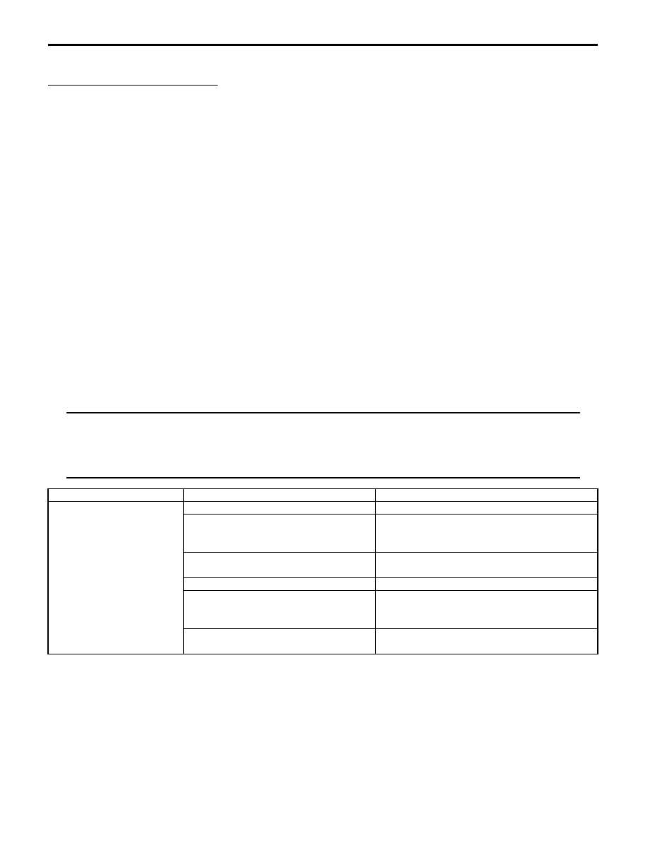
Rear End door Window Defogger Symptom Diagnosis

S6JB0A9504001

NOTE

• Use of SUZUKI scan tool makes it easy to check whether a faulty condition is on the input side or 

output side of BCM. For checking procedure, refer to “Diagnosis Using Output Test Function of 
SUZUKI Scan Tool” under “Scan Tool Data in Section 10B”.

• Check each part in the order from the top of the following list.


Condition

Possible cause

Correction / Reference Item

Rear end door window 
defogger does not 
operate

Circuit fuse blown

Replace fuse and check for short circuit.

Rear end door window defogger relay 
faulty

Check rear end door window defogger relay 
referring to “Rear End Door Window Defogger 
Relay Inspection”.

Defogger wire faulty

Check defogger wire referring to “Rear End 
Door Window Defogger Wire Inspection”.

Wiring or grounding faulty

Repair circuit.

HVAC control module faulty

Check HVAC control module referring to 
“HVAC Control Module and Its Circuits 
Inspection in Section 7B”.

BCM faulty

Replace after making sure that none of above 
parts is faulty.

Glass / Windows / Mirrors:  9E-4

Power Window Control System Symptom Diagnosis

S6JB0A9504002

Power Door Mirror Control System Symptom Diagnosis

S6JB0A9504003

Door Mirror Heater Symptom Diagnosis (If Equipped)

S6JB0A9504004

NOTE

• Use of SUZUKI scan tool makes it easy to check whether a faulty condition is on the input side or 

output side of BCM. For checking procedure, refer to “Diagnosis Using Output Test Function of 
SUZUKI Scan Tool” under “Scan Tool Data in Section 10B”.

• Check each part in the order from the top of the following list.


Condition

Possible cause

Correction / Reference Item

All power windows do not 
operate

Circuit fuse blown

Replace fuse and check for short circuit.

Power window main switch faulty

Check power window main switch referring to 
“Power Window Main Switch Inspection”.

Ignition switch faulty

Check ignition switch referring to “Ignition 
Switch Inspection in Section 9C”.

Wiring or grounding faulty

Repair circuit.

Only one power window 
does not operate

Power window main switch faulty

Check power window main switch referring to 
“Power Window Main Switch Inspection”.

Power window sub switch faulty

Check power window sub switch referring to 
“Power Window Sub Switch Inspection”.

Wiring and/or coupler faulty

Check wiring and/or coupler.

Power window regulator faulty

Check window regulator.

Power window motor faulty

Check power window motor. 

Wiring or grounding faulty

Repair circuit.

Condition

Possible cause

Correction / Reference Item

All power mirrors do not 
operate

Circuit fuse blown

Replace fuse and check for short circuit.

Power door mirror switch faulty

Check power door mirror switch referring to 
“Power Door Mirror Switch Inspection”.

Wiring or grounding faulty

Repair circuit.

One power mirror does 
not operate

Power door mirror switch faulty

Check power door mirror switch referring to 
“Power Door Mirror Switch Inspection”.

Power door mirror actuator faulty

Check actuator refraining to “Power Door 
Mirror Actuator Inspection”.

Wiring or grounding faulty

Repair circuit.

Condition

Possible cause

Correction / Reference Item

All door mirror heaters 
does not operate

Circuit fuse blown

Replace fuse and check for short circuit.

Mirror heater relay faulty

Check mirror heater relay referring to “Door 
Mirror Heater Relay Inspection (If Equipped)”.

Wiring or grounding faulty

Repair circuit.

HVAC control module faulty

Check HVAC control module referring to 
“HVAC Control Module and Its Circuits 
Inspection in Section 7B”.

BCM faulty

Replace after making sure that none of above 
parts is faulty.

Only one door mirror 
heater does not operate

Door mirror heater faulty

Check door mirror heater referring to “Door 
Mirror Heater Inspection (If Equipped)”.

Wiring or grounding faulty

Repair circuit.

9E-5 Glass / Windows / Mirrors: 

Repair Instructions

Windshield Removal and Installation

S6JB0A9506001

Removal

1) Clean both inside and outside of glass and around it.
2) Remove wiper arms and cowl top garnish.
3) Remove windshield side garnish.
4) Using tape, cover body surface around glass to 

prevent any damage.

5) Remove rear view mirror, sun visor and front pillar 

trims (right & left).

6) If necessary, remove instrument panel. Refer to 

“Instrument Panel Removal and Installation in 
Section 9C”.

7) If necessary, remove head lining. Refer to “Head 

Lining Removal and Installation in Section 9H”.

8) Remove (or cut) windshield molding.
9) Drill hole with eyeleteer (1) through adhesive and let 

piano string through it.

10) Cut adhesive all around windshield (1) with piano 

string (2). When using tool, windshield knife (3), to 
cut adhesive, be careful not to cause damage to 
windshield. Use wire to cut adhesive along lower 
part of windshield.

NOTE
Use piano string (2) as close to glass as 
possible so as to prevent damage to body 
and instrument panel.


11) Using knife (1), smoothen adhesive (2) remaining on 

body side (3) so that it is 1 – 2 mm (0.039 – 0.078 
in.) thick all around.

NOTE
Before using knife (1), clean it with alcohol or 
the like to remove oil from it.


I2RH01950040-01

I3RH0A950006-01

I2RH01950042-01

Glass / Windows / Mirrors:  9E-6

12) When reusing windshield, remove the adhesive (1) 

from it, using care not to damage primer coated 
surface (2).

Installation

1) Using cleaning solvent, clean windshield edge where 

windshield glass is to be adhered. (Let it dry for more 
than 10 minutes.)

2) To determine installing position of glass (1) to body 

(2), position glass against body so that clearance 
between upper end of glass (1) and body (2) is 
approximately 5.5 mm (0.217 in.) and clearances 
between each side end (right & left) of glass (1) and 
body (2) are even. Then mark mating marks on glass 
(1) and body (2) as shown. Upper clearance can be 
adjusted by moving glass stoppers position.

Windshield clearance
“a”: approx. 5.5 mm (0.217 in.)

3) Clean contact surfaces of old adhesive (4), paint or 

bare metal thoroughly.
If surfaces of paint or bare metal come out, apply 
primer (2) for body with caution not to apply primer 
(2) to surface of adhesive remaining on body.

NOTE

• Be sure to refer to primer maker’s 

instruction for proper handling and drying 
time.

• Do not touch body and old adhesive 

surfaces where glass is to be adhered.


4) Install new molding to glass.
5) Clean glass surface to be adhered to body with 

clean cloth. If cleaning solvent is used, let it dry for 
10 minutes or more.

Cleaning Area for windshield (distance from the 
edge of glass or molding)
30 – 50 mm (1.18 – 1.97 in.)

6) Install new fastener (1) to windshield (2).

I2RH01950043-01

I5JB0A950003-01

1. Do not apply primer
3. Apply primer

I2RH01950046-01

I5JB0A950004-02


Content   ..  496  497  498  499   ..