Suzuki Grand Vitara JB416 / JB420 / JB419. Manual - part 487
 

  Index      Suzuki     Suzuki Grand Vitara JB416 / JB420 / JB419 - service repair manual 2007 year


Search            


Content   ..  485  486  487  488   ..


Suzuki Grand Vitara JB416 / JB420 / JB419. Manual - part 487


9B-33 Lighting Systems: 

Auto-On Headlight Sensor Inspection (If 
Equipped)

S6JB0A9206030

1) Disconnect negative (–) cable at battery.
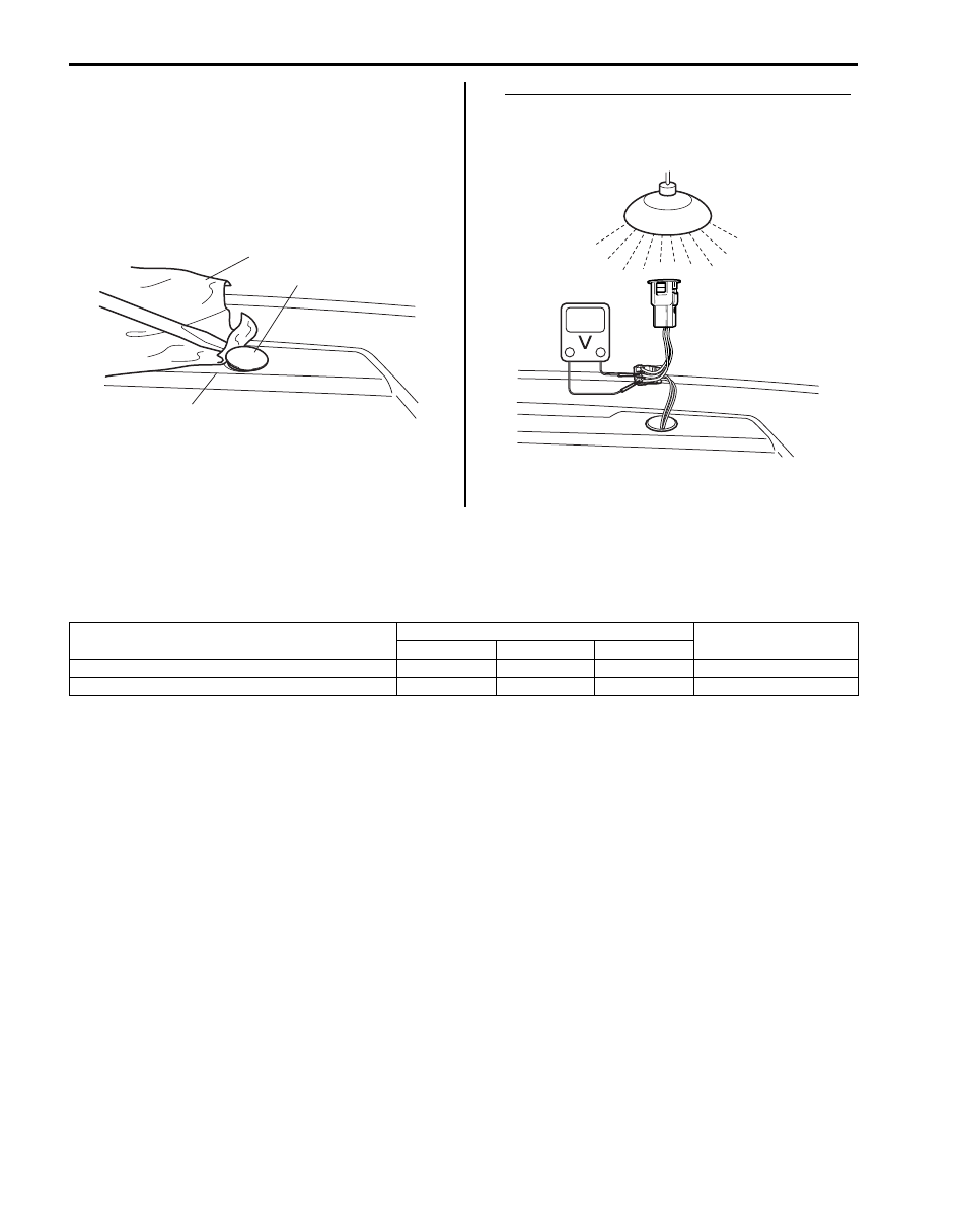
2) Remove auto-on headlight sensor (1) located on the 

passenger side of the dashboard (2). Be careful not 
to damage the sensor (1) and dashboard by using 
rag (3).

3) Measure voltage between white wire terminal and 

black wire terminal at the following condition.
If measured voltage is out of specification, replace 
sensor.

Auto-on headlight sensor voltage specifications
Cover the sensor lens with hand: 0.4 V
Light the sensor lens with incandescent lamp 
100 W: 3 – 4.5 V

Specifications

Tightening Torque Specifications

S6JB0A9207001

Reference:
For the tightening torque of fastener not specified in this section, refer to “Fastener Information in Section 0A”.

2

1

3

I5JB0A920038-01

I5JB0A920039-01

Fastening part

Tightening torque

Note

N

m

kgf-m

lb-ft

Height sensor bolt

10

1.0 

7.5

)

Height sensor nut

10

1.0 

7.5

)

Instrumentation / Driver Info. / Horn:  9C-1

Body, Cab and Accessories

Instrumentation / Driver Info. / Horn

Precautions

Precautions in Diagnosing Troubles for Combination Meter

S6JB0A9300001

Combination meter uses signals (information) from each control module by CAN communication to control 
speedometer, tachometer, fuel meter (petrol engine model), engine coolant temp meter, warning light and indicator 
light (other than air bag warning light, headlight leveling warning light, rear fog light and turn signal indicator light). 
Therefore, check that no DTC is detected in each module before performing combination meter symptom diagnosis. If 
any DTC is detected, correct trouble indicated by that DTC troubleshooting first.

General Description

CAN Communication System Description

S6JB0A9301001

Refer to “CAN Communication System Description: For Petrol Engine Model in Section 1A” or “CAN Communication 
System Description: For Diesel Engine Model in Section 1A” for
 CAN communication system description. Combination 
meter communicates control data with each control module as follows.

Combination Meter Transmission Data

BCM

Combination

Meter

DATA 

Transmit

Fuel level percent signal

I7RW01930001-01

9C-2 Instrumentation / Driver Info. / Horn: 

Combination Meter Reception Data

NOTE
*1: Petrol engine model
*2: Diesel engine model
*3: ESP

® model


ECM

BCM

Keyless

 Start

 Control
 Module

(if equipped)

DATA

Recive

Combination 

Meter

4WD

 Control 
 Module 

(if equipped)

TCM

(A/T

 model)

Engine speed signal

Immobilizer indicator light control

signal

Vehicle speed signal

Engine coolant temperature signal

Fuel level signal

MIL control signal

Transmission range sensor signal

Diagnostic trouble code (DTC)

Brake fluid level switch signal

(brake warning light control signal)

Driver side seat belt buckle switch

signal (seat belt reminder light control

signal)

Charging system warning light signal

(charge warning light control signal) 

Engine oil pressure switch signal

(oil pressure warning light control

signal)

Parking brake switch signal

(brake warning light control signal)

Lighting switch signal

Door switch signal 

(open door warning light control signal)

ABS indication signal

EBD indication signal

(brake warning light control signal)

4WD mode indicator control signal 

Key indicator light control signal

ESP    status signal

ABS/ESP 

Control
Module

"CRUSE" and "SET" indicator light

control signal

Automatic transmission mode indicator

light control signal

Electric load signal

Transmission warning light control

signal

Diesel particulate filter warning light

control signal

Injection waning light control signal

Red stop warning light control signal      

Glow ingicator light control signal

Fuel filter warning light control signal

*1

*1

*2

*2
*2

*2
*2

*3

I6JB0A930002-02

Instrumentation / Driver Info. / Horn:  9C-3

Auto Volume Control System Description (If Equipped)

S6JB0A9301002

Function of auto volume control system is to vary sound volume according to changes of vehicle speed. How much 
sound volume varies depends on selected level.

Reference Correlation Chart of Vehicle Speed and Sound Volume

[A]: Vehicle speed

[C]: Acceleration

[E]: Increase

[B]: Sound volume

[D]: Deceleration

[F]: Decrease

[A]

[E]

[F]

[B]

[E]

[F]

[C]

[D]

I6RS0B930004-01


Content   ..  485  486  487  488   ..