Suzuki Grand Vitara JB416 / JB420 / JB419. Manual - part 396
 

  Index      Suzuki     Suzuki Grand Vitara JB416 / JB420 / JB419 - service repair manual 2007 year


Search            


Content   ..  394  395  396  397   ..


Suzuki Grand Vitara JB416 / JB420 / JB419. Manual - part 396


7B-75 Air Conditioning System: 

Installation

1) Install HVAC unit by reversing removal procedure, 

noting the following items.
• When installing each part, be careful not to catch 

any wiring harness.

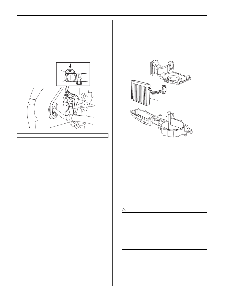
• For diesel engine model, connect quick joint (1) to 

HVAC unit, and then push lock plate (2) 
completely in arrow direction.

• Replenish specified amount of compressor oil to 

compressor suction side referring to “Precautions 
on Replenishing Compressor Oil”.

• Install the padding (1) to the installation hole 

uniformly.

• Fill engine coolant to radiator referring to “Cooling 

System Flush and Refill: For Petrol Engine Model 
in Section 1F” 
or “Cooling System Refilling: For 
Diesel Engine Model in Section 1F”.

• Enable air bag system referring to “Enabling Air 

Bag System in Section 8B”.

• Evacuate and charge system. Refer to “Operation 

Procedure for Charging A/C with Refrigerant”.

A/C Evaporator Removal and Installation

S6JB0A7206009

Removal

1) Remove HVAC unit referring to “HVAC Unit Removal 

and Installation”.

2) Remove evaporator (1) from HVAC unit by 

disassembling HVAC unit.

3) Remove evaporator temperature sensor from 

evaporator.

Installation
Reverse removal procedure to install A/C evaporator 
nothing the following instructions.
• Install evaporator temperature sensor onto evaporator 

referring to “A/C Evaporator Temperature Sensor 
Removal and Installation”.

A/C Evaporator Inspection

S6JB0A7206010

1) Check evaporator fins for blockage. If found clogged, 

use compressed air to clean the fins.

CAUTION

!


• Do not use water for cleaning of 

evaporator.

• Be careful not to damage evaporator fins. 

If evaporator fin is bent, straighten it by 
using a screwdriver or pair of pliers. If any 
leakage is found from fitting or tube, repair 
or replace evaporator.


2) Check inlet and outlet fittings for crack or scratch. 

Repair them as required.

3. Heater hose

2

3

1

I5JB0B720012-01

1

I5JB0A720045-02

Air Conditioning System:  7B-76

A/C Evaporator Temperature Sensor Removal 
and Installation

S6JB0A7206011

Removal

1) Remove A/C evaporator (1) referring to “A/C 

Evaporator Removal and Installation”.

2) Remove A/C evaporator temperature sensor (2) 

from evaporator.

Installation

1) Identify evaporator by the following tables.

NOTE
As for Evaporator, there are 4 varieties 
depending on the internal structure.


2) Install evaporator temperature sensor onto 

evaporator in a correct position as shown in figure.

CAUTION

!


Mis-position causes insufficiency cooling 
and damaged of A/C system.


Evaporator 

type

Selection condition

A

LH steering vehicle

Evaporator with 
protection rubber (1)

B

Evaporator without 
protection rubber (2)

C

RH steering vehicle

Evaporator with 
protection rubber

D

Evaporator without 
protection rubber

3. Protection rubber

1

2

I5JB0A720046-01

1

2

3

I5GEB4720001-01

[A]: Evaporator type A 

5. Holding part fixed to fin of 6th 

line from the left-side edge

[B]: Evaporator type B

6. Sensor part fixed to fin of 5th 

line from the left-side edge

[C]: Evaporator type C

7. Holding part fixed to fin of 3rd 

line from the left-side edge

[D]: Evaporator type D

8. Sensor part fixed to fin of 8th 

line from the right-side edge

1. Evaporator temperature 

sensor

9. Holding part fixed to fin of 6th 

line from the right-side edge

2. Evaporator

10. Sensor part fixed to fin of 5th 

line from the right-side edge

3. 34.5 mm (1.36 in.)

11. Holding part fixed to fin of 3rd 

line from the right-side edge

4. Sensor part fixed to fin of 8th 

line from the left-side edge

4

2

5

6

7

9

8

11

10

3

[A]

[B]

2

3

2

3

[C]

[D]

2

3

1

1

1

1

I5GEB4720002-03

7B-77 Air Conditioning System: 

A/C Evaporator Temperature Sensor Inspection

S6JB0A7206012

Check resistance between A/C evaporator temperature 
sensor terminals. If check result is not in specification, 
replace A/C evaporator temperature sensor with the new 
one.

A/C evaporator temperature sensor resistance
11.2 – 11.5 k

 at 0 °C (32 °F)

3.8 – 3.9 k

 at 25 °C (77 °F)

Expansion Valve On-Vehicle Inspection

S6JB0A7206013

Refer to “A/C System Performance Inspection”.

Expansion Valve Removal and Installation

S6JB0A7206014

Removal

1) Recover refrigerant from the A/C system with 

recovery and recycling equipment referring to 
“Recovery” in “Operation Procedure for Charging A/
C with Refrigerant”.

2) Loosen a bolt (1) and remove pipes from expansion 

valve (2).

3) Loosen bolts (3) and remove expansion valve.

Installation

1) Reverse removal nothing the following instructions.

• Apply compressor oil to O-ring of expansion valve 

and pipes.

2) Evacuate and charge system according to 

“Operation Procedure for Charging A/C with 
Refrigerant”.

1. Expansion valve

(k

)

11.4

3.9
3.3

0

32

25
77

30
86

(˚C)

(˚F)

Resistance

Temperature

I5JB0A720090-03

IYSQ01720049-01

3

1

2

2

I5JB0A720048-02

Air Conditioning System:  7B-78

A/C Refrigerant Pressure Sensor and Its Circuit 
Inspection (Petrol Engine Model)

S6JB0A7206015

1) Disconnect A/C refrigerant pressure sensor 

connector.

2) Turn ignition switch to ON position.
3) Check if voltage between “GRY/RED” wire terminal 

and “GRY/GRN” wire terminal of A/C refrigerant 
pressure sensor connector is 4.75 V to 5.25 V.
If not, check A/C refrigerant pressure sensor circuit.

4) Connect A/C refrigerant pressure sensor connector 

with ignition switch turned OFF.

5) Connect manifold gauge set to the charging valves.
6) Check A/C refrigerant pressure sensor voltage of 

ECM connector referring to “A/C System Inspection 
at ECM”.
If voltage is not as specified below, replace A/C 
refrigerant pressure sensor.

A/C refrigerant pressure sensor voltage 
specifications (A/C refrigerant pressure measured 
by manifold gauge)
0.8 MPa (8.0 kg/cm

2

, 116 psi): Approx. 1.46 – 1.71 V

1.4 MPa (14 kg/cm

2

, 203 psi): Approx. 2.28 – 2.53 V

1.6 MPa (16 kg/cm

2

, 232 psi): Approx. 2.55 – 2.80 V

1.8 MPa (18 kg/cm

2

, 261 psi): Approx. 2.82 – 3.03 V

A/C Refrigerant Pressure Sensor and Its Circuit 
Inspection (Diesel Engine Model)

S6JB0A7206047

1) Connect manifold gauge set to the charging valves.
2) Check output voltage for A/C refrigerant pressure 

sensor (1) between each sensor terminal, and then 
compare measured voltage with specified voltage in 
graph.
If it does not show such characteristic as shown in 
graph, replace refrigerant pressure sensor with new 
one.

A/C Refrigerant Pressure Sensor Removal and 
Installation

S6JB0A7206016

Removal

1) Recover refrigerant from the A/C system with the 

recovery and recycling equipment referring to 
“Recovery” in “Operation Procedure for Charging A/
C with Refrigerant”.

2) Disconnect negative (–) cable from battery.
3) Disconnect A/C refrigerant pressure sensor 

connector.

4) Remove A/C refrigerant pressure sensor (1) from 

liquid pipe (2).

4.5

3.6

0.42

180

2600

3300

(V)

(kPa)

1

I5JB0B720013-01

[A]: Petrol engine model
[B]: Diesel engine model

1

[A]

[B]

2

1

2

3

I6JB0A720011-01


Content   ..  394  395  396  397   ..