Suzuki Grand Vitara JB416 / JB420 / JB419. Manual - part 375
 

  Index      Suzuki     Suzuki Grand Vitara JB416 / JB420 / JB419 - service repair manual 2007 year


Search            


Content   ..  373  374  375  376   ..


Suzuki Grand Vitara JB416 / JB420 / JB419. Manual - part 375


7A-10 Heater and Ventilation: 

Repair Instructions

Blower Unit and Heater Unit Components

S6JB0A7106001

As heater unit and blower unit are incorporated as an 
assembly named HVAC unit, they cannot be removed 
individually from vehicle body.
Same HVAC unit is used whether vehicle is equipped 
with A/C system or not.
For components of HVAC unit, refer to “HVAC Unit 
Components in Section 7B”
.

HVAC Unit Removal and Installation (for Vehicle 
without A/C)

S6JB0A7106002

Refer to “HVAC Unit Removal and Installation in Section 
7B”.

HVAC Air Filter Removal and Installation (for 
Vehicle without A/C)

S6JB0A7106003

Refer to “HVAC Air Filter Removal and Installation in 
Section 7B”.

HVAC Air Filter Inspection (for Vehicle without 
A/C)

S6JB0A7106004

Refer to “HVAC Air Filter Inspection in Section 7B”.

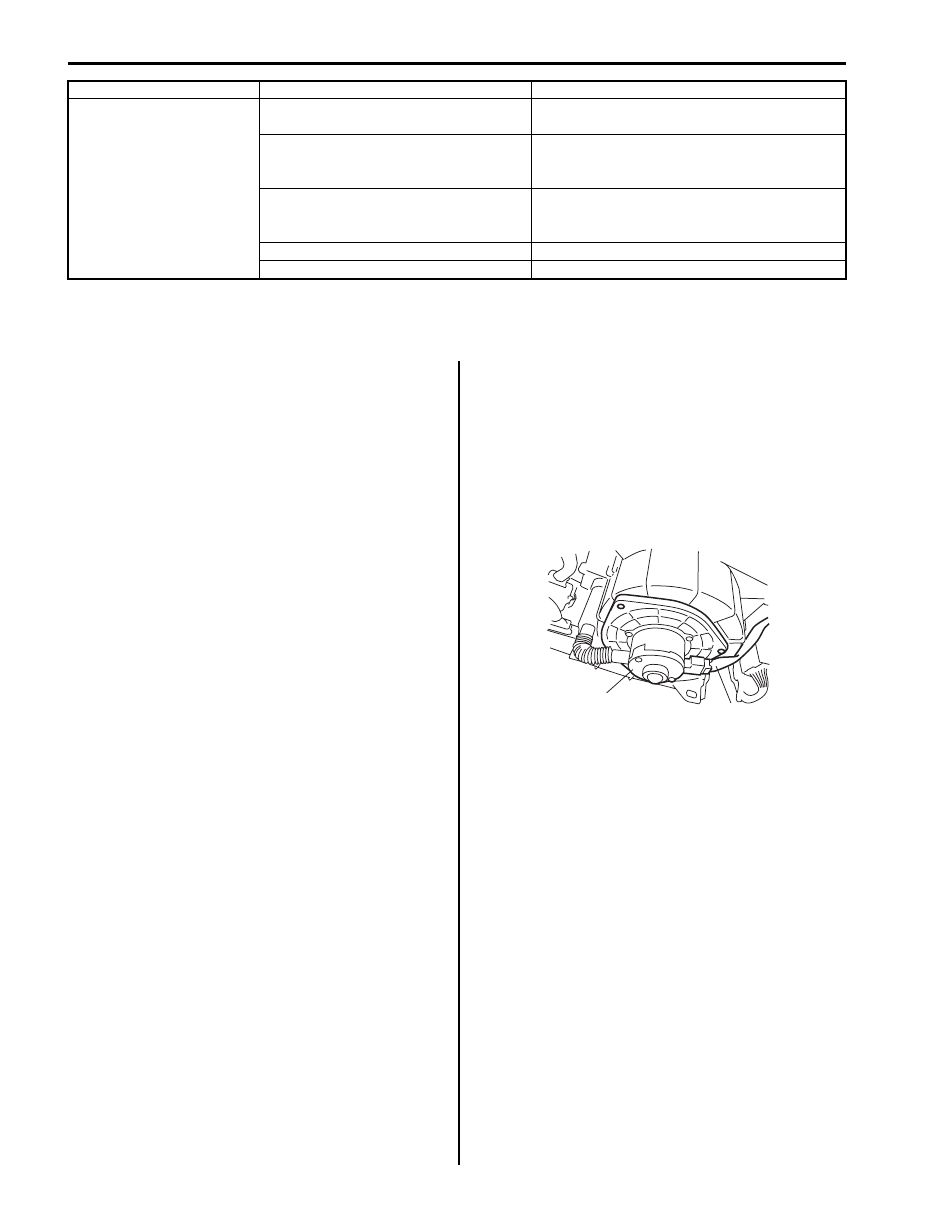
Blower Motor Removal and Installation

S6JB0A7106005

Removal

1) Disconnect negative (–) cable at battery.
2) Disable air bag system referring to “Disabling Air 

Bag System in Section 8B”.

3) Disconnect blower motor lead wire (2) at coupler.
4) Remove blower motor (1) from HVAC unit.

Installation

1) Reverse removal procedure for installation.
2) Enable air bag system referring to “Enabling Air Bag 

System in Section 8B”.

Heating performance is 
poor (for additional heater 
system)

Fuse blown

Check related fuses and check for short circuit 
to ground.

Additional heater relays faulty

Check additional heater relays referring to 
“Additional Heater Relay Inspection (Diesel 
Engine Model)”
.

Additional heater assembly faulty

Check additional heater assembly referring to 
“Additional Heater Assembly On-Vehicle 
Inspection (Diesel Engine Model)”
.

ECM faulty

Check ECM.

Wiring or grounding faulty

Repair as necessary.

Condition

Possible cause

Correction / Reference Item

1

2

I5JB0A710006-03

Heater and Ventilation:  7A-11

Blower Motor Inspection

S6JB0A7106006

• Check continuity between terminals as shown in the 

figure.
If check result is continuity, proceed to next operation 
check. If not, replace.

• Check for operation and electric current.

a. Put blower motor (1) in a soft-jawed vise.
b. Connect battery to blower motor as shown.
c. Check if blower motor operates smoothly without 

noise.

d. Check if ammeter indicates the specified current.

If measured current is out of specification, replace 
blower motor.

Specified current for blower motor
Approx. 12 A at 12 V

Blower Motor Controller Removal and 
Installation

S6JB0A7106007

Removal

1) Disconnect negative (–) cable at battery.
2) Disable air bag system referring to “Disabling Air 

Bag System in Section 8B”.

3) Remove glove box.
4) Remove passenger lower member.
5) Disconnect blower motor controller coupler (3).
6) Remove blower motor controller (1) by loosening its 

fastening screws (2).

Installation

1) Reverse removal procedure.
2) Enable air bag system referring to “Enabling Air Bag 

System in Section 8B”.

I5JB0A710007-01

1

I5JB0A710008-01

3

1

2

I5JB0A710009-01

7A-12 Heater and Ventilation: 

Blower Motor Controller Inspection

S6JB0A7106008

Check controller for operation as follows.
• Using service wire, connect battery positive terminal 

to “1” terminal (1) of blower motor controller (6) and 
battery negative terminal to “2” terminal (2) of blower 
motor controller.

• Using bulb (3.4 W) (4) and service wire, connect 

battery positive terminal to “3” terminal (3) of blower 
motor controller as shown figure.

• Arrange 3 new 1.5 V batteries (5) in series (check that 

total voltage is 4.5 – 5.0 V) and connect its positive 
terminal to “3” terminal of blower motor controller and 
negative terminal to “2” terminal of blower motor 
controller. Then, check that bulb lights. If bulb does 
not light under the above conditions, replace blower 
motor controller.

Blower Motor Relay Inspection

S6JB0A7106009

1) Disconnect negative (–) cable at battery.
2) Remove blower motor relay (1) from vehicle.
3) Check that there is no continuity between terminal 

“c” and “d”. If there is continuity, replace relay.

4) Connect battery positive (+) terminal to terminal “b” 

of relay.
Connect battery negative (–) terminal to terminal “a” 
of relay.
Check continuity between terminal “c” and “d”.
If there is no continuity when relay is connected to 
the battery, replace relay.

Heater Core Removal and Installation

S6JB0A7106010

Removal

1) Remove instrument panel referring to “Instrument 

Panel Removal and Installation in Section 9C”.

2) Remove HVAC unit. Refer to “HVAC Unit Removal 

and Installation in Section 7B”.

3) Remove heater core pipe clamp and then, pull out 

heater core (1) from HVAC unit.

6

6

1

1

2

2

3

3

4

5

I5JB0A710010-01

1

“d”

“a”

“b”

“c”

I5JB0A710011-01

1

I5JB0A710012-02

Heater and Ventilation:  7A-13

Installation
Install heater core by reversing removal procedure, 
noting the following items.
• When installing heater core, be careful not to damage 

fins of heater core.

• When installing each part, be careful not to catch any 

wiring harness.

Additional Heater Relay Inspection (Diesel 
Engine Model)

S6JB0A7106024

1) Disconnect negative (–) cable at battery.
2) Remove additional heater relay No.1 (1), No.2 (2) 

and No.3 (3) from vehicle.

3) Check that there is no continuity between terminal 

“c” and “d”. If there is continuity, replace relay.

4) Connect battery positive (+) terminal to terminal “b” 

of relay and battery negative (–) terminal to terminal 
“a” of relay.
Check that there is continuity between terminal “c” 
and “d”.If there is no continuity, replace relay.

Additional Heater Assembly On-Vehicle 
Inspection (Diesel Engine Model)

S6JB0A7106025

1) Disconnect negative (–) cable at battery.
2) Disconnect wires from additional heater terminals.

NOTE
Make alignment marks (1) on wires and 
additional heater body for a guide during 
reinstallation, if necessary.


3) Check resistance between each terminal of 

additional heater and vehicle body ground. If 
resistance is out of specification, replace additional 
heater assembly with new one.

Additional heater terminal resistance
0.55 – 0.65 

 at 20 °C (68 °F)

a

b

c

d

1

2

3

I5JB0B710005-01

1

1

I5JB0B710006-01

I5JB0B710007-02


Content   ..  373  374  375  376   ..