Suzuki Grand Vitara JB416 / JB420 / JB419. Manual - part 355
 

  Index      Suzuki     Suzuki Grand Vitara JB416 / JB420 / JB419 - service repair manual 2007 year


Search            


Content   ..  353  354  355  356   ..


Suzuki Grand Vitara JB416 / JB420 / JB419. Manual - part 355


5B-67 Manual Transmission/Transaxle: For Diesel Engine Model

Countershaft Assembly Disassembly and 
Reassembly

S6JB0A5226025

Disassembly

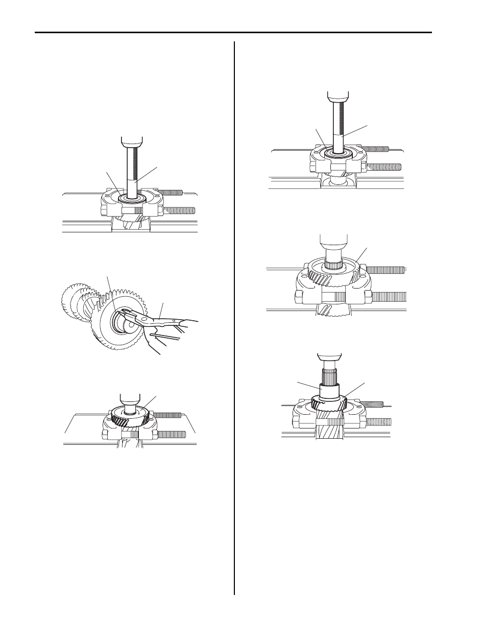
1) Remove countershaft rear bearing (1) using bearing 

puller, special tool and hydraulic press.

Special tool
(A):  09925–98221

2) Remove circlip (1) from countershaft using snap ring 

pliers (2).

3) Remove countershaft 5th gear (1) using bearing 

puller and hydraulic press.

4) Remove countershaft front bearing (1) using bearing 

puller, special tool and hydraulic press.

Special tool
(A):  09925–98221

5) Remove circlip from countershaft using snap ring 

pliers and then remove countershaft reduction gear 
(1) using bearing puller and hydraulic press.

6) Remove countershaft 3rd gear (1) and spacer (2) 

using bearing puller and hydraulic press.

1

(A)

I5JB0B520082-01

1

2

I5JB0B520083-02

1

I5JB0B520084-01

1

(A)

I5JB0B520085-01

1

I5JB0B520086-01

1

2

I5JB0B520087-01

Manual Transmission/Transaxle: For Diesel Engine Model 5B-68

Reassembly

1) Clean all components thoroughly, inspect them for 

any abnormality and replace with new one as 
necessary.

2) Drive in countershaft 5th gear (1) to countershaft (2) 

facing its long flange (3) side downward in figure 
using bearing puller, special tools and hydraulic 
press.

Special tool
(A):  09913–75510
(B):  09924–07710

3) Install circlip to countershaft using snap ring pliers.
4) Drive in countershaft rear bearing (1) using bearing 

puller, special tool and hydraulic press.

Special tool
(A):  09913–76010

5) Drive in countershaft 3rd gear (1) to countershaft (2) 

facing its long flange (3) side downward in figure 
using bearing puller, special tool and hydraulic 
press.

Special tool
(A):  09924–74590

6) Drive in countershaft high speed gear spacer (1) to 

countershaft (2) using bearing puller, special tool and 
hydraulic press.

Special tool
(A):  09913–85210

1

2

(A)

(B)

1

3

I5JB0B520088-03

(A)

1

I5JB0B520089-01

1

(A)

1

3

2

I5JB0B520090-03

(A)

1

2

I5JB0B520091-01

5B-69 Manual Transmission/Transaxle: For Diesel Engine Model

7) Drive in countershaft reduction gear (1) to 

countershaft (2) facing its long flange (3) side 
downward in figure using bearing puller, special tool 
and hydraulic press.

Special tool
(A):  09913–84510

8) Select circlip (1) that will make thrust clearance “a” of 

synchronizer hub 0.15 mm (0.006 in) or less and 
install it.

Available circlip thickness

9) Drive in countershaft front bearing (1) using bearing 

puller, special tool and hydraulic press.

Special tool
(A):  09913–76010

Reverse Idle Gear Assembly Disassembly and 
Reassembly

S6JB0A5226033

Disassembly

1) Drive out reverse idle gear shaft pin using special 

tool.

Special tool
(A):  09922–85811

2) Remove reverse idle gear shaft (1), reverse idle gear 

washer (2), reverse idle gear (3) and reverse idle 
gear needle bearing (4) from reverse idle gear case 
(5).

1.50 mm (0.059 in.)

1.68 mm (0.066 in.)

1.59 mm (0.063 in.)

2

1

3

(A)

I5JB0B520092-02

I5JB0B520093-01

(A)

1

I5JB0B520094-02

(A)

I5JB0B520095-01

1

2

2

3

4

5

I5JB0B520109-01

Manual Transmission/Transaxle: For Diesel Engine Model 5B-70

Reassembly

1) Apply oil to reverse idle gear needle bearing (1), and 

then install reverse idle gear shaft (2), washer (3), 
needle bearing and reverse idle gear (4) to reverse 
idle gear case (5).

2) Drive in reverse idle gear shaft pin using special tool.

Special tool
(A):  09922–85811

Countershaft and Reverse Idle Gear Inspection

S6JB0A5226026

• Check chamfered teeth of gear for damage and 

excessive wear, and replace as necessary.

• Check spline portions and replace parts if excessive 

wear is found.

• Check bearing for smooth rotation and replace it if 

abnormality is found.

Manual Transmission Adapter Case 
Disassembly and Assembly

S6JB0A5226030

Disassembly
Remove oil seal (1) from adapter case using special tool.

Special tool
(A):  09913–50121

Assembly

1) Install new oil seal (1) to adapter case (2) facing its 

spring side upward in figure using special tool and 
hammer and then apply grease to oil seal lip.

Special tool
(A):  09913–75520

“A”:  Grease 99000–25010 (SUZUKI Super Grease A)

Installation position oil seal
“a”: 1.5 – 2.5 mm (0.059 – 0.098 in.)

2

3

3

4

1

5

I5JB0B520110-01

(A)

I5JB0B520095-01

(A)

1

I5JB0A520086-01

I5JB0B520098-01


Content   ..  353  354  355  356   ..