Suzuki Grand Vitara JB416 / JB420 / JB419. Manual - part 346
 

  Index      Suzuki     Suzuki Grand Vitara JB416 / JB420 / JB419 - service repair manual 2007 year


Search            


Content   ..  344  345  346  347   ..


Suzuki Grand Vitara JB416 / JB420 / JB419. Manual - part 346


5B-31 Manual Transmission/Transaxle: For Petrol Engine Model

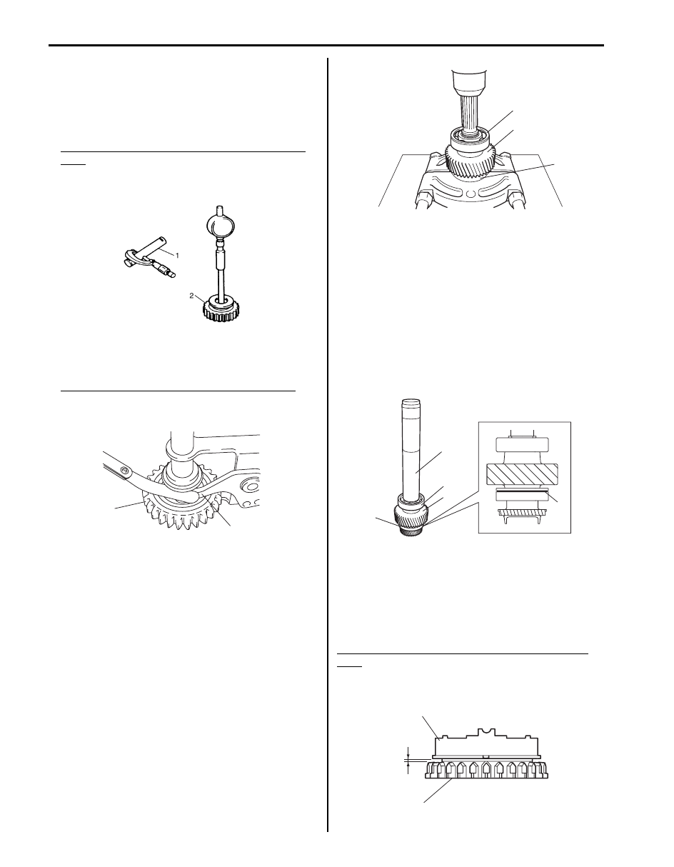
• Check oil clearance between reverse idle gear (2) and 

shaft (1) measuring inside diameter “a” of gear and 
diameter “b” of shaft and calculate as follows:

If clearance exceeds limit, replace gear and shaft.

Oil clearance “c” between reverse idle gear and 
shaft
Standard: 0.016 – 0.045 mm (0.0006 – 0.0018 in.)
Limit: 0.13 mm (0.005 in.)

• Check clearance between reverse idle gear (2) and 

lever (1) of reverse gear shift link.
If clearance exceeds limit, replace gear and lever.

Clearance between reverse idle gear and lever
Standard: 0.05 mm – 0.25 mm (0.002 – 0.010 in.)
Limit: 0.5 mm (0.020 in.)

Output Shaft Disassembly and Assembly

S6JB0A5216027

Disassembly

1) Remove output shaft rear snap ring.
2) Apply bearing puller to output shaft front bearing (1), 

and drive out output shaft front bearing, output shaft 
gear (2) and output shaft rear bearing (3) all at once 
from output shaft using press.

Assembly

1) Clean all components thoroughly, inspect them for 

any abnormality and replace with new ones as 
necessary.

2) Put front bearing (1) onto output shaft facing groove 

(4) side to output shaft gear (2) and drive in output 
shaft front bearing, output shaft gear and output 
shaft rear bearing (3) all together using special tool 
and hammer.

Special tool
(A):  09940–51710

3) Install new output shaft rear snap ring.

Output Shaft Inspection

S6JB0A5216028

Check clearance “a” between ring (2) and output shaft 
(1), each chamfered teeth of gear, ring and sleeve, then 
determine parts replacement.

Clearance between synchronizer ring and output 
shaft
Standard “a”: 1.0 – 1.4 mm (0.040 – 0.055 in.)
Service limit “a”: 0.5 mm (0.020 in.)

Clearance “c”

=

“b”

“a”

IYSQ01522123-01

1

2

I5JB0A520080-01

3

2

1

I5JB0A520081-01

(A)

3

2

1

4

I5JB0A520082-01

“a”

1

2

I5JB0A520083-01

Manual Transmission/Transaxle: For Petrol Engine Model 5B-32

Manual Transmission Front Case Disassembly 
and Assembly

S6JB0A5216029

Disassembly
Remove pump seal (1) and oil seal (2) from front case 
using special tools.

Special tool
(A):  09941–64511
(B):  09930–30104

Assembly

1) Set new oil seal to front case with its spring side 

facing rear case side.

2) Install oil seal until it becomes flush with case 

surface using special tool and hammer and apply 
grease to oil seal lip.

Special tool
(A):  09940–51710 

:  Grease 99000–25010 (SUZUKI Super Grease A)

3) Install pump seal to front case using special tool and 

hammer.

Special tool
(A):  09913–75810

Manual Transmission Adapter Case 
Disassembly and Assembly

S6JB0A5216030

Disassembly
Remove oil seal (1) from adapter case using special tool.

Special tool
(A):  09913–50121

Assembly

1) Set new oil seal to adapter case with its spring side 

facing rear case side.

2) Install oil seal until it becomes flush with case 

surface using special tool and hammer and apply 
grease to oil seal lip.

Special tool
(A):  09913–85210

:  Grease 99000–25010 (SUZUKI Super Grease A)

(B)

(A)

1

1

2

I5JB0A520084-02

(A)

I5JB0A520085-02

(A)

I5JB0A520088-01

(A)

1

I5JB0A520086-01

(A)

I5JB0A520087-01

5B-33 Manual Transmission/Transaxle: For Petrol Engine Model

Extension Case Assembly Components

S6JB0A5216032

13

14-1

5

12

1

7

9

15

8

(a)

(a)

1217G

10

1217G

1217G

OIL

5

OIL

6

OIL

4

A

11

(a)

4

A

2

16

(b)

14-2

(b)

17

3

I6JB0A521001-02

1. Front extension case

12. Extension to transmission bolt

2. Intermediate shaft

13. Breather hose

3. Rear extension case

14-1. Damper (with bracket)

4. Oil seal

: Apply grease 99000-25010 to oil seal lip.

14-2. Damper (without bracket)

5. Bearing

15. Damper bracket (if equipped)

6. Needle bearing

16. Damper nut

7. Hook

17. Damper bolt

8. Hook bolt

: 23 N

⋅m (2.3 kgf-m, 17.0 lb-ft)

9. Oil filler plug

: Apply sealant 99000-31260 to plug thread.

: 50 N

⋅m (5.0 kgf-m, 36.5 lb-ft)

10. Oil drain plug

: Apply sealant 99000-31260 to plug thread.

: Do not reuse.

11. Extension case bolt

: Apply transmission oil.

Manual Transmission/Transaxle: For Petrol Engine Model 5B-34

Extension Case Assembly Removal and 
Installation

S6JB0A5216033

Removal
Remove extension case assembly referring to “Manual 
Transmission Assembly Dismounting and Remounting: 
For Petrol Engine Model”.

Installation
Reverse removal procedure for installation of extension 
case assembly, noting the following points.
• Extension to transmission bolt: 23 N

⋅m (2.3 kgf-m, 

17.0 lb-ft)

• Fill gear oil to extension case referring to “Extension 

Case Oil Change: For Petrol Engine Model”.

Extension Case Disassembly and Reassembly

S6JB0A5216034

Disassembly

1) Remove rear extension case and damper with 

bracket (if equipped) from front extension case.

2) Disassemble rear extension case (2) as follows, if 

necessary.
a) Remove oil seal (3) from rear extension case 

using flat end rod or the like.

b) Remove needle bearing (1) using special tools.

Special tool
(A):  09913–76010
(B):  09944–66020

3) Remove intermediate shaft from front extension 

case.

4) Remove oil seal from front extension case using flat 

end rod or the like, if necessary.

5) Remove intermediate front bearing and/or 

intermediate rear bearing using press (1) and 
bearing puller (2), if necessary.

Reassembly

1) Install intermediate front bearing (1) and/or 

intermediate rear bearing (2) using press (3) and 
bearing puller (4).

2) Install oil seal (1) to front extension case (2) until it 

become flush with case using special tool, and then 
apply grease to oil seal lip.

NOTE
When installing oil seal, face its spring side 
inward.


“A”:  Grease 99000–25010 (SUZUKI Super 
Grease A)

Special tool
(A):  09951–46010

(A)

(B)

2

3

1

I6JB01520003-01

1

2

I6JB01520004-01

3

2

4

1

I6JB01520005-01

1, “A”

(A)

2

I6JB01520006-01


Content   ..  344  345  346  347   ..