Suzuki Grand Vitara JB416 / JB420 / JB419. Manual - part 305
 

  Index      Suzuki     Suzuki Grand Vitara JB416 / JB420 / JB419 - service repair manual 2007 year


Search            


Content   ..  303  304  305  306   ..


Suzuki Grand Vitara JB416 / JB420 / JB419. Manual - part 305


5A-11 Automatic Transmission/Transaxle: 

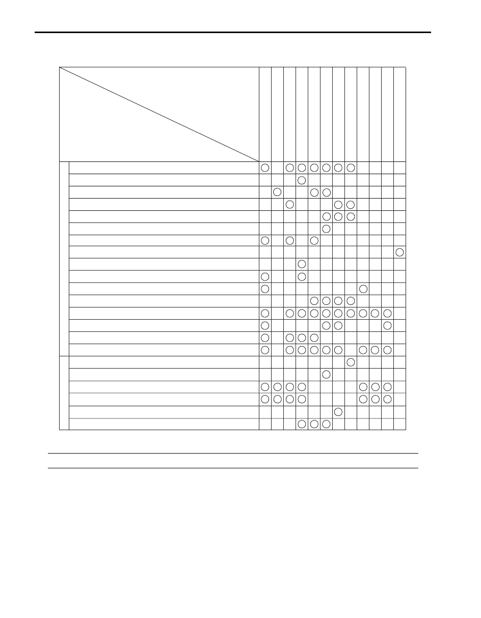
Electronic Shift Control Input / Output Table

S6JB0A5101005

NOTE
*1: For E-OBD model (Except RH steering vehicle not equipped with rear fog light model)


INPUT / OUTPUT

CONTROL

Accelerator effective position

Throttle position

Coolant temperature

Engine torque

Engine speed

A/C ON/OFF

Brake light switch

Vehicle speed

Cruise control signal (if equipped with cruise control system)

P/N mode switch

"3" position switch

Input shaft speed sensor

ATF temperature sensor

Output shaft speed sensor

4L/N switch (if equipped)

Torque reduction request

Shift switch

Lock-up control

Gear Shift control

4th gear inhibit control

Slope shift control

Cruise shift control

Slip control

Line pressre control

Torque control

Overrun control

Reverse control

Squat control

Speed meter indicate

Output

Input

Shift solenoid valve-A

Shift solenoid valve-B

Pressure control solenoid valve

TCC pressure control solenoid valve

Slip control signal *1

I5JB0D510004-04

Automatic Transmission/Transaxle:  5A-12

Brake Interlock System Description

S6JB0A5101006

Shift Lock Solenoid Control
This system consists of shift lock solenoid control 
system and interlock cable control system.
The shift lock solenoid control system is so designed 
that the select lever can not be shifted from “P” range 
position unless the ignition switch is turned ON and the 
brake pedal is depressed. And the interlock cable control 
system is so designed that the select lever cannot be 
shifted from “P” range position unless the ignition switch 
is turned to ACC or ON position. Also, the ignition key 
cannot be pulled out of the key slot unless the select 
lever is in “P” range.

A/T Diagnosis General Description

S6JB0A5101007

This vehicle is equipped with an electronic transmission 
control system, which control the automatic shift up and 
shift down timing, TCC operation, etc. suitably to vehicle 
driving conditions.
TCM has an On-Board Diagnosis system which detects 
a malfunction in this system and abnormality of those 
parts that influence the engine exhaust emission.
When diagnosing a trouble in the transmission including 
this system, be sure to have full understanding of the 
outline of “On-Board Diagnostic System Description” and 
each item in “Precautions in Diagnosing Trouble” an
execute diagnosis according to “A/T System Check” to 
obtain correct result smoothly.

NOTE
There are two type of On-Board Diagnostic 
System, E-OBD system and non-E-OBD 
system.


On-Board Diagnostic System Description

S6JB0A5101008

For E-OBD Model
For automatic transmission control system, TCM has the 
following functions. Refer to “Inspection of TCM and Its 
Circuits”
.
• When the ignition switch is turned ON with the engine 

at a stop, malfunction indicator lamp (MIL) (1) turns 
ON to check the bulb of the MIL.

• When TCM detects a malfunction in A/T control 

system TCM desires turning on malfunction indicator 
lamp (MIL) and stores malfunction DTC in TCM 
memory.
(If it detects that continuously 3 driving cycles are 
normal after detecting a malfunction, however, it 
makes MIL turn OFF although DTC stored in its 
memory will remain.)

• It is possible to communicate through DLC (3) by 

using not only SUZUKI scan tool (2) but also OBD 
generic scan tool. (Diagnostic information can be 
checked and erased by using a scan tool.)

1

2

3

I5JB0A510011-01

5A-13 Automatic Transmission/Transaxle: 

2 Driving cycle detection logic
The malfunction detected in the first driving cycle is 
stored in TCM memory (in the form of pending DTC and 
freeze frame data) but the malfunction indicator lamp 
does not light at this time. It lights up at the second 
detection of same malfunction also in the next driving 
cycle.

Pending DTC
Pending DTC means a DTC detected and stored 
temporarily at 1 driving cycle of the DTC which is 
detected in the 2 driving cycle detection logic.

Freeze frame data
TCM stores the engine and driving conditions at the 
moment of the detection of a malfunction in its memory. 
This data is called “Freeze frame data”.
Therefore, it is possible to know engine and driving 
conditions (e.g., whether the engine was warm or not, 
where the vehicle was running or stopped) when a 
malfunction was detected by checking the freeze frame 
data.

For Non-E-OBD Model
For automatic transmission control system, TCM has the 
following functions. Refer to “Inspection of TCM and Its 
Circuits”.
• When ignition switch is turned ON with no malfunction 

in A/T control system is detected, transmission 
warning light (1) lights for about 2 seconds after 
ignition switch is turned ON and then goes OFF for 
bulb check.

• When TCM detects a malfunction in A/T control 

system, it indicates transmission warning light (1) and 
stores malfunction DTC in its memory.

• It is possible to communicate with TCM through data 

link connector (DLC) (3) by using SUZUKI scan tool 
(2). Diagnostic information can be checked and 
erased by using SUZUKI scan tool.

2 Driving cycle detection logic
The malfunction detected in the first driving cycle is 
stored in TCM memory (in the form of pending DTC and 
freeze frame data) but the malfunction indicator lamp 
does not light at this time. It lights up at the second 
detection of same malfunction also in the next driving 
cycle.

Pending DTC
Pending DTC means a DTC detected and stored 
temporarily at 1 driving cycle of the DTC which is 
detected in the 2 driving cycle detection logic.

1

2

3

I6JB0A510002-01

Automatic Transmission/Transaxle:  5A-14

Schematic and Routing Diagram

Electronic Shift Control Input / Output Diagram

S6JB0A5102003

NOTE
*1: For E-OBD model (Except RH steering vehicle not equipped with rear fog light model)
*2: For E-OBD model
*3: For non-E-OBD model


INPUT

OUTPUT

TCM

ECM
-Accelerator pedal position
-Coolant temperature
-Engine torque
-Engine speed
-A/C ON/OFF
-Brake light switch
-Vehicle speed
-Cruise control signal
 (if equipped with cruise
  control system)

BCM
-P/N mode signal

Gear shift control

4th gear inhibit control

Slope shift control

Cruise shift control (if equipped
with cruise control system)

Lock up control

Slip control (* 1)

Torque control

Line pressure control

Overrun control

Reverse control

Squat control

P/N mode switch

Input shaft speed
sensor

Output shaft speed
sensor

"3" position switch

ATF temp. sensor

4L/N switch (if equipped)

Shift switch
- Range "P" signal
- Range "R" signal
- Range "N" signal
- Range "D" signal
- Range "2" signal
- Range "L" signal

Fail safe function

Self diagnosis

Warning function

ECM
-Torque red. request
-Slip control signal (*1)
-Shift position signal

COMB. METER
-Shift indicator
-POWER mode lamp
-MIL (*2)
-Transmission  
 warning light (*3)

Shift solenoid valve-A

Shift solenoid valve-B

TCC pressure control
solenoid valve

Pressure control
solenoid valve

Signal on CAN
communincation line

I5JB0D510003-03


Content   ..  303  304  305  306   ..