Suzuki Grand Vitara JB416 / JB420 / JB419. Manual - part 296
4F-32 Electronic Stability Program:
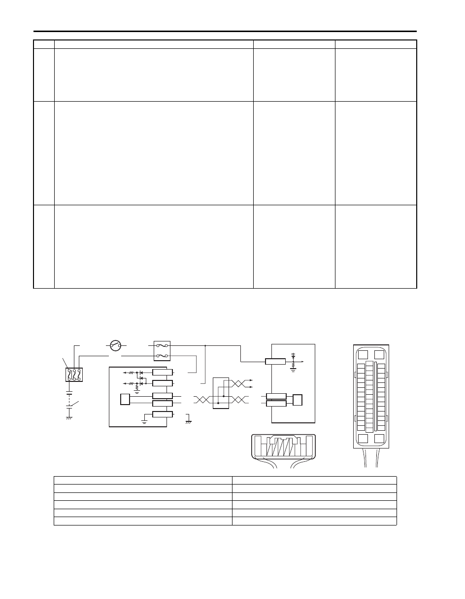
DTC C1037: Steering Angle Sensor Power Supply Failure
S6JB0A4604022
Wiring Diagram
4
Check yaw rate / G sensor assembly power supply
circuit
1) Measure voltage between connector terminal “L39-3”
and “L39-5” with ignition switch turned ON.
Is it 10 – 14 V?
Substitute a known-
good yaw rate / G
sensor assembly and
recheck.
Go to Step 5.
5
Check yaw rate / G sensor assembly power supply
circuit
1) Turn ignition switch to OFF position.
2) Disconnect ESP
® control module connector.
3) Check for proper connection to ESP
® control module
connector terminals at “E53-31” and “E53-37”.
4) If OK, then measure voltage between connector terminal
“E53-37” and vehicle body ground with ignition switch
turned ON.
Is it 12 V?
Go to Step 6.
“PNK/WHT” wire circuit
is shorted to power
circuit.
6
Check yaw rate / G sensor assembly power supply
circuit
1) Measure resistance between the following points.
• Between terminal “E53-37” of module connector and
terminal “L39-3” of sensor terminal.
• Between terminal “E53-31” of module connector and
terminal “L39-5” of sensor terminal.
Are resistance less than 2
Ω
?
Substitute a known-
good ESP
® hydraulic
unit / control module
assembly and recheck.
“PNK/WHT” and/or
“PNK/GRN” wire circuit
open or high resistance.
Step
Action
Yes
No
[A]
E53
16
1
15
2
3
4
5
6
7
8
9
10
11
12
13
14
17
18
19
20
21
22
23
24
25
26
27
28
29
30
31
32
33
34
35
36
37
38
39
40
41
42
43
44
45
46
47
E53-13
E53-44
RED
WHT
RED
WHT
WHT
GRN/ORN
G45-3
G45-1
BLK
G45-2
G45-10
G45-9
BLK/YEL
WHT/GRN
1
WHT
[B]
G45
10 9
3 2 1
2
3
4
5
6
7
8
9
6
12V
E53-35
I6JB0A460005-01
[A]: ESP
® control module connector (viewed from terminal side)
5. Steering angle sensor
[B]: Steering angle sensor connector (viewed from harness side)
6. CAN driver
1. Battery
7. Junction connector
2. Main fuse box
8. Other control modules are communicated with CAN
3. Ignition switch
9. ESP
® hydraulic unit / control module assembly
4. Junction block assembly