Suzuki Grand Vitara JB416 / JB420 / JB419. Manual - part 293
 

  Index      Suzuki     Suzuki Grand Vitara JB416 / JB420 / JB419 - service repair manual 2007 year


Search            


Content   ..  291  292  293  294   ..


Suzuki Grand Vitara JB416 / JB420 / JB419. Manual - part 293


4F-20 Electronic Stability Program: 

ESP

® Warning Light Does Not Come ON at Ignition Switch ON

S6JB0A4604010

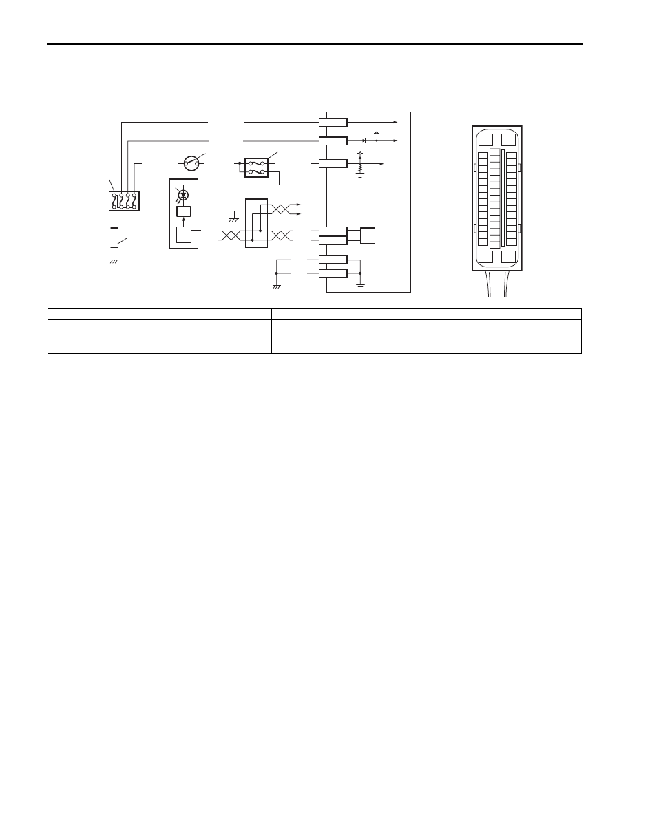
Wiring Diagram

Circuit Description
Operation (ON/OFF) of ESP

® warning light is controlled by ESP® control module through light driver module in 

combination meter.
If ESP

® system is in good condition, ESP® control module turns ESP® warning light ON at the ignition switch ON, 

keeps it ON for 2 seconds and then turns it OFF. If an abnormality in the system is detected, ESP

® warning light is 

turned ON continuously by ESP

® control module. Also, it is turned ON continuously by light driver module when the 

connector of ESP

® control module is disconnected.

3

4

2

1

[A]

E53-16

E53-47

12V

12V

E53-32

E53-1

E53-35

GRN/ORN

PPL/RED

BLK/YEL

WHT/GRN

WHT/RED

WHT/BLU

BLK

BLK

BLK

RED

WHT

RED

WHT

E53-13
E53-44

11

10

9

5

7

8

6

8

E53

16

1

15

2

3

4

5

6

7

8

9

10

11

12

13

14

17

18

19

20

21

22

23

24

25

26

27

28

29

30

31

32

33

34

35

36

37

38

39

40

41

42

43

44

45

46

47

I6JB01460013-01

[A]: ESP

® control module connector (viewed from terminal side)

4. Junction block assembly

8. CAN driver

1. Battery

5. Combination meter

9. Junction connector

2. Main fuse box

6. ESP

® warning light 

10. Other control modules are communicated with CAN

3. Ignition switch

7. Light driver module

11. ESP

® hydraulic unit / control module assembly

Electronic Stability Program:  4F-21

Troubleshooting

Step

Action

Yes

No

1

1) Turn ignition switch to ON position.

Do other warning lights come ON?

Go to Step 2.

Go to Step 3.

2

1) Connect scan tool to DLC with ignition switch turned 

OFF.

2) Turn ignition switch to ON position and check DTC.

Is there DTC U1073?

Go to “DTC U1073: 
Control Module 
Communication Bus 
Off” for tro
ubleshooting.

Substitute a known-
good combination meter 
and recheck. If ESP

® 

warning light remains 
OFF, substitute a 
known-good ESP

® 

hydraulic unit / control 
module assembly and 
recheck.

3

Is Circuit fuse for combination meter in good condition?

Go to Step 4.

Replace fuse and check 
for short circuit to 
ground.

4

1) Check CAN communication circuit between combination 

meter and ESP

®, control module referring to “DTC 

U1073: Control Module Communication Bus Off”

Is CAN communication circuit in good condition?

Go to Step 5.

Repair or replace.

5

1) Remove combination meter with ignition switch turned 

OFF.

2) Check for proper connection to “PPL/RED” and “BLK” 

wire of combination meter connector.

3) If OK, turn ON ignition switch and measure voltage at 

“PPL/RED” wire of combination meter connector and 
vehicle body ground.

Is it 10 – 14 V?

Go to Step 6.

Repair power supply 
circuit for combination 
meter.

6

1) Measure resistance between “BLK” wire of combination 

meter connector and vehicle body ground.

Is resistance less than 2 

?

Replace combination 
meter.

“BLK” circuit open or 
high resistance.

4F-22 Electronic Stability Program: 

ESP

® Warning Light Comes ON Steady

S6JB0A4604011

Wiring Diagram
Refer to “ESP

® Warning Light Does Not Come ON at Ignition Switch ON”.

Circuit Description
Operation (ON/OFF) of ESP

® warning light is controlled by ESP® control module through light driver module in 

combination meter.
If ESP

® system is in good condition, ESP® control module turns ESP® warning light ON at the ignition switch ON, 

keeps it ON for 2 seconds and then turns it OFF. If an abnormality in the system is detected, ESP

® warning light is 

turned ON continuously by ESP

® control module. Also, it is turned ON continuously by light driver module when the 

connector of ESP

® control module is disconnected.

Troubleshooting

Step

Action

Yes

No

1

1) Perform diagnostic trouble code check.

Is there any DTC(s)?

Go to applicable DTC 
diag. flow.

Go to Step 2.

2

Are main fuses for pump motor and solenoid valves in good 
condition?

Go to Step 3.

Replace fuse and check 
circuit for short to 
ground.

3

1) Turn ignition switch to OFF.
2) Disconnect ESP

® control module connector.

3) Check for proper connection to ESP

® control module 

connector at terminals “E53-35”, “E53-16” and “E53-47”.

4) If OK then turn ignition switch to ON position and 

measure voltage between terminal “E53-35” and vehicle 
body ground.

Is it 10 – 14 V?

Go to Step 4.

“GRN/ORN” circuit 
open.

4

1) Turn ignition switch to OFF position.
2) Check for proper connection to ESP

® control module 

connector at terminals “E53-1” and “E53-32”.

3) If OK then turn ignition switch to ON position and 

measure voltage between each terminal of “E53-1”, 
“E53-32” and vehicle body ground.

Are they 10 – 14 V?

Go to Step 5.

“WHT/RED” and/or 
“WHT/BLU” circuit 
open.

5

1) Turn ignition switch to OFF and measure resistance 

between each terminal of “E53-16”, “E53-47” and vehicle 
body ground.

Is resistance less than 2 

?

Go to Step 6.

Ground circuit for ESP

® 

control module open or 
high resistance.

6

1) Check CAN communication circuit between combination 

meter and ESP

® control module referring to “DTC 

U1073: Control Module Communication Bus Off”.

Is CAN communication circuit in good condition?

Substitute a known-
good combination meter 
and recheck. If ABS 
warning light remains 
ON, substitute a known-
good ESP

® hydraulic 

unit / control module 
assembly and recheck.

Repair or replace.

Electronic Stability Program:  4F-23

Serial Data Link Circuit Check

S6JB0A4604012

Wiring Diagram

Inspection

3

4

2

1

12V

12V

E53-32

E53-1

E53-35

GRN/ORN

PPL/RED

BLK/YEL

WHT/GRN

WHT/RED

WHT/BLU

E53-16

E53-47

BLK

BLK

BLK

RED

WHT

RED

WHT

E53-13
E53-44

PPL/WHT

12V

+BB

E53-33

[A]

11

12

10

9

G

G1

5

7

6

13

E53

16

1

15

2

3

4

5

6

7

8

9

10

11

12

13

14

17

18

19

20

21

22

23

24

25

26

27

28

29

30

31

32

33

34

35

36

37

38

39

40

41

42

43

44

45

46

47

8

8

GRN/ORN

14

B

I6JB0A460003-01

[A]: ESP

® control module connector (viewed from terminal side)

5. Combination meter

10. To ECM, TCM, BCM, SDM and 4WD control module

1. Battery

6. ESP

® warning light

11. Junction connector

2. Main fuse box

7. Light driver module

12. Other control modules are communicated with CAN

3. Ignition switch

8. CAN driver

13. ESP

® hydraulic unit / control module assembly

4. Junction block assembly

9. Data link connector (DLC)

14. Steering angle sensor

Step

Action

Yes

No

1

1) Turn ignition switch to ON position.

Does ESP

®

 warning light come ON?

Go to Step 2.

Go to Step 6.

2

1) Turn ignition switch to OFF position.

Are the condition of the fuses concerning pump motor and 
solenoid valves good?

Go to Step 3.

Replace fuse and check 
for short.

3

1) Disconnect ESP

® control module connector.

2) Check for proper connection to ESP

® control module 

connector at terminal “E53-35”.

3) If OK then turn ignition switch to ON position and 

measure voltage between terminal “E53-35” and vehicle 
body ground.

Is it 10 – 14 V?

Go to Step 4.

“GRN/ORN” wire circuit 
open.

4

1) Turn ignition switch to OFF position.
2) Check for proper connection to ESP

® control module 

connector at terminals “E53-1” and “E53-32”.

3) If OK then turn ignition switch to ON position and 

measure voltage between each terminal of “E53-1”, 
“E53-32” and vehicle body ground.

Are they 10 – 14 V?

Go to Step 5.

“WHT/RED” and/or 
“WHT/BLU” wire circuit 
open.

5

1) Turn ignition switch to OFF position.
2) Check for proper connection to ESP

® control module 

connector at terminals “E53-16” and “E53-47”.

3) If OK, measure resistance between each terminal of 

“E53-16”, “E53-47” and vehicle body ground.

Are resistance less than 2 

?

Go to Step 6.

Ground circuit for ESP

® 

control module open or 
high resistance.


Content   ..  291  292  293  294   ..