Suzuki Grand Vitara JB416 / JB420 / JB419. Manual - part 287
 

  Index      Suzuki     Suzuki Grand Vitara JB416 / JB420 / JB419 - service repair manual 2007 year


Search            


Content   ..  285  286  287  288   ..


Suzuki Grand Vitara JB416 / JB420 / JB419. Manual - part 287


4E-40 ABS: 

Front and Rear Wheel Speed Sensor On-Vehicle 
Inspection

S6JB0A4506004

Output Voltage Inspection

1) Disconnect negative (–) cable from battery.
2) Hoist vehicle a little.
3) Disconnect wheel speed sensor connector.
4) Disconnect wheel speed grommet from vehicle body.
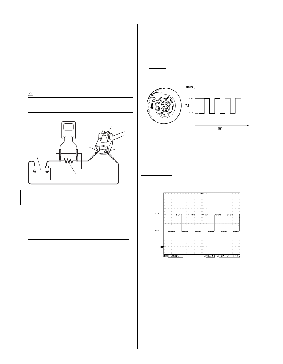
5) Set up measuring devices as shown in figure, the 

resistance to 115 

Ω and the power supply voltage to 

12 V.

CAUTION

!


Incorrect voltage and/or wrong connection 
cause damage to wheel speed sensor.


6) Measure voltage at resistance without wheel 

rotation.
If voltage is out of specification, check sensor, 
mating encoder and their installation conditions.

Voltage at the resistance (115 

) without wheel 

rotation
680 to 960 mV

7) Measure voltage at resistance with wheel rotation 

and confirm voltage alternately changes between 
high and low voltages.
If voltage does not change with wheel rotation, check 
sensor, mating encoder and their installation 
conditions.

Voltage at the resistance (115 

) with wheel 

rotation
High voltage “a”: 1360 to 1930 mV
Low voltage “b”: 680 to 960 mV

Reference
When using oscilloscope for this check, check if peak-to-
peak voltage and waveform meet specification.

Peak-to-peak Voltage at the resistance (115 

) with 

wheel rotation
High voltage “a”: 1360 to 1930 mV
Low voltage “b”: 680 to 960 mV

1. Wheel speed sensor connector

4. “BLK” wire terminal

2. Resistance (115 

Ω)

5. Power supply (12 V)

3. “WHT” wire terminal

V

4

1

3

2

5

I5JB0A450026-03

[A]: Voltage

[B]: Time

I5JB0A450027-01

I5JB0A450028-02

ABS: 4E-41

Front Wheel Speed Sensor Removal and 
Installation

S6JB0A4506005

Removal

1) Disconnect negative (–) cable from battery.
2) Disconnect front wheel speed sensor coupler (1).
3) Hoist vehicle and remove wheel.
4) Remove harness clamp, clamp bolts (2) and 

grommet (3).

5) Remove front wheel speed sensor (4) from knuckle.

CAUTION

!


• Do not pull wire harness when removing 

front wheel speed sensor.

• Do not cause damage to surface of front 

wheel speed sensor and do not allow dust, 
etc. to enter its installation hole.


Installation

1) Check that no foreign material is attached to sensor 

(1) and mating encoder (2).

2) Install it by reversing removal procedure.

Tightening torque
Front wheel speed sensor bolt (a):  11 N·m (1.1 
kgf-m, 8.0 lb-ft)
Front wheel speed sensor harness clamp bolt  
(b):  11 N·m (1.1 kgf-m, 8.0 lb-ft)

CAUTION

!


Do not pull or twist wire harness more than 
necessary when installing front wheel speed 
sensor.


3) Check that there is no clearance between sensor 

and knuckle.

Front and Rear Wheel Speed Sensor Inspection

S6JB0A4506006

Check sensor for damage.
If any malcondition is found, replace.

Rear Wheel Speed Sensor Removal and 
Installation

S6JB0A4506008

Removal

1) Disconnect negative (–) cable from battery.
2) Disconnect rear wheel speed sensor coupler (1).
3) Hoist vehicle and remove wheel.
4) Remove harness clamp (4) and clamp bolts (2).

2

1

3

4

I5JB0A450029-01

[A]: OK

[B]: NG

[A]

[B]

2

2

(a)

2

1

(b)

I5JB0A450030-01

I5JB0A450031-01

4E-42 ABS: 

5) Remove rear wheel speed sensor (3) from knuckle.

CAUTION

!


• Do not pull wire harness when removing 

rear wheel speed sensor.

• Do not cause damage to surface of rear 

wheel speed sensor and do not allow dust, 
etc. to enter its installation hole.


Installation
Reverse removal procedure for installation noting the 
following.
• Check that no foreign material is attached to sensor 

(1) and mating encoder (2).

• Be sure to install wheel speed sensor (1) and its bolt 

at the correct (upper) position as shown in figure. 
Tighten sensor bolt and harness clamp bolts to 
specified torque.

Tightening torque
Rear wheel speed sensor bolt (a):  11 N·m (1.1 kgf-
m, 8.0 lb-ft)
Rear wheel speed sensor harness clamp bolt 
(b):  11 N·m (1.1 kgf-m, 8.0 lb-ft)

CAUTION

!


Do not pull or twist wire harness more than 
necessary when installing rear wheel speed 
sensor.


• Check that there is no clearance between sensor and 

brake back plate.

Front Wheel Encoder On-Vehicle Inspection

S6JB0A4506010

Before inspect front wheel encoder, remove front drive 
shaft or front wheel spindle referring to “Front Drive Shaft 
Assembly Removal and Installation: Front in Section 3A” 
or “Front Wheel Hub Assembly Removal and Installation 
in Section 2B”.
• Check encoder (1) for being crack, damaged or 

deformed.

• Turn wheel and check if encoder rotation is free from 

eccentricity and looseness.

• Check that no foreign material is attached.
If any faulty is found, repair or replace. Refer to “Front 
Wheel Hub Assembly Removal and Installation in 
Section 2B”.

3

1

2

4

I5JB0A450032-02

[A]: OK

[B]: NG

[A]

[B]

2

1

(a)

(b)

1

1

I5JB0A450033-01

1

I5JB0A450034-01

ABS: 4E-43

Front Wheel Encoder Removal and Installation

S6JB0A4506011

CAUTION

!


Front wheel encoder is included in front 
wheel hub assembly. If front wheel encoder 
needs to replaced, replace it as a front wheel 
hub assembly.


For removal and installation of front wheel hub 
assembly, referring to “Front Wheel Hub Assembly 
Removal and Installation in Section 2B”.

Rear Wheel Encoder On-Vehicle Inspection

S6JB0A4506012

Before inspect rear wheel encoder, remove rear drive 
shaft referring to “Rear Drive Shaft Disassembly and 
Assembly: Rear in Section 3A”.
• Check encoder (1) for being crack, damaged or 

deformed.

• Turn wheel and check if encoder rotation is free from 

eccentricity and looseness.

• Check that no foreign material is attached.

If any faulty is found, repair or replace. Refer to “Rear 
Wheel Hub Assembly Removal and Installation in 
Section 2C”.

Rear Wheel Encoder Removal and Installation

S6JB0A4506013

CAUTION

!


Rear wheel encoder is included in rear wheel 
hub assembly. If rear wheel encoder needs to 
replaced, replace it as a rear wheel hub 
assembly.


For removal and installation of front wheel hub 
assembly, referring to “Rear Wheel Hub Assembly 
Removal and Installation in Section 2C”.

1

I5JB0A450035-01


Content   ..  285  286  287  288   ..