Suzuki Grand Vitara JB416 / JB420 / JB419. Manual - part 283
4E-24 ABS:
DTC Detecting Condition
The ABS (ESP
®) control module monitors the output from the valve.
When the output of each valve exceeds the specified value compared with the signal sent from ABS (ESP
®) control
module, this DTC is set.
DTC Troubleshooting
DTC C1057: ABS (ESP
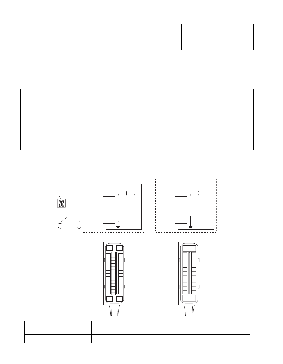
®) Control Module Power Supply Circuit Failure
S6JB0A4504015
Wiring Diagram
[B]: Non-ESP
® model
2. Main fuse box
6. Solenoid valve power supply driver
(transistor)
[C]: ESP
® control module connector (viewed from terminal
side)
3. ESP
® hydraulic unit / control module
assembly
7. Solenoid valve driver
[D]: ABS control module connector (viewed from terminal
side)
4. ABS hydraulic unit / control module
assembly
Step
Action
Yes
No
1
Was “ABS Check” performed?
Go to Step 2.
2
1) Turn ignition switch to OFF position.
2) Disconnect ABS (ESP
®) control module connector.
3) Check for proper connection to ABS (ESP
®) control
module connector at terminal “E03-14” (or “E53-1”).
4) If OK, then measure voltage between terminal “E03-14”
(or “E53-1”) of module connector and “E03-13”, “E03-26”
(or “E53-16”, “E53-47”).
Are they 10 – 14 V?
Substitute a known-
good ABS (ESP
®)
hydraulic unit /control
module assembly and
recheck.
“WHT/RED” or “BLK”
circuit open.
WHT/RED
1
2
3
12V
E53-1
BLK
BLK
E53-16
E53-47
WHT/RED
4
12V
E03-14
BLK
BLK
E03-13
E03-26
[A]
[B]
[D]
E03
15
16
17
18
19
20
21
22
23
24
25
2
3
4
5
6
7
8
9
10
11
12
1
13
14
26
[C]
E53
16
1
15
2
3
4
5
6
7
8
9
10
11
12
13
14
17
18
19
20
21
22
23
24
25
26
27
28
29
30
31
32
33
34
35
36
37
38
39
40
41
42
43
44
45
46
47
I6JB01450009-02
[A]: ESP
® model
[D]: ABS control module connector (viewed from
terminal side)
3. ESP
® hydraulic unit / control module assembly
[B]: Non-ESP
® model
1. Battery
4. ABS hydraulic unit / control module assembly
[C]: ESP
® control module connector
(viewed from terminal side)
2. Main fuse box